DECAN_S2_Admin(Eng_Ver4.5).pdf - 第258页
8-1 Feeder Setup Chapter8. Feeder Setup 8.1. Feeder [F4] The ‘Feeder’ submenu edits data related to tap e feeder , stick feeder , a nd tray feeder . The user can spec i fy the part to be in st alled on each f eeder , tea…
8-1
Feeder Setup
Chapter8. Feeder Setup
8.1. Feeder [F4]
The ‘Feeder’ submenu edits data related to tape feeder, stick feeder, and tray feeder. The
user can specify the part to be installed on each feeder, teach the pick-up position, and test
the component pick-up. When this submenu is selected, the initial screen is for the tape
feeder screen.
8.1.1. Feeder Base
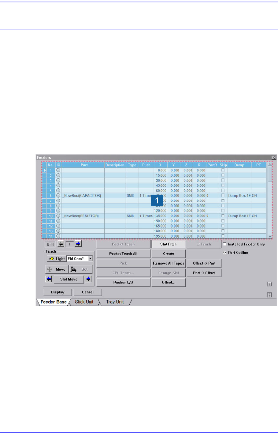
When the feeder base is selected, the following dialog box is displayed and the data on
feeder base can be edited.
Figure8.1 “Feeder: Feeder Base” dialog box
1: Grid group
<Grid> group
Display the status of various devices installed on the feeder base including the feeder
type and edit the installation position.
<No> column
A serial number of the feeder base slot. Air pressure type feeder base has 52 slots.
<IO> column
Displays the LED color for the status of the tape feeder installed in the
corresponding slot.
8-2
Advanced Chip Shooter DECAN S2 Administrator’s Guide
<Part> column
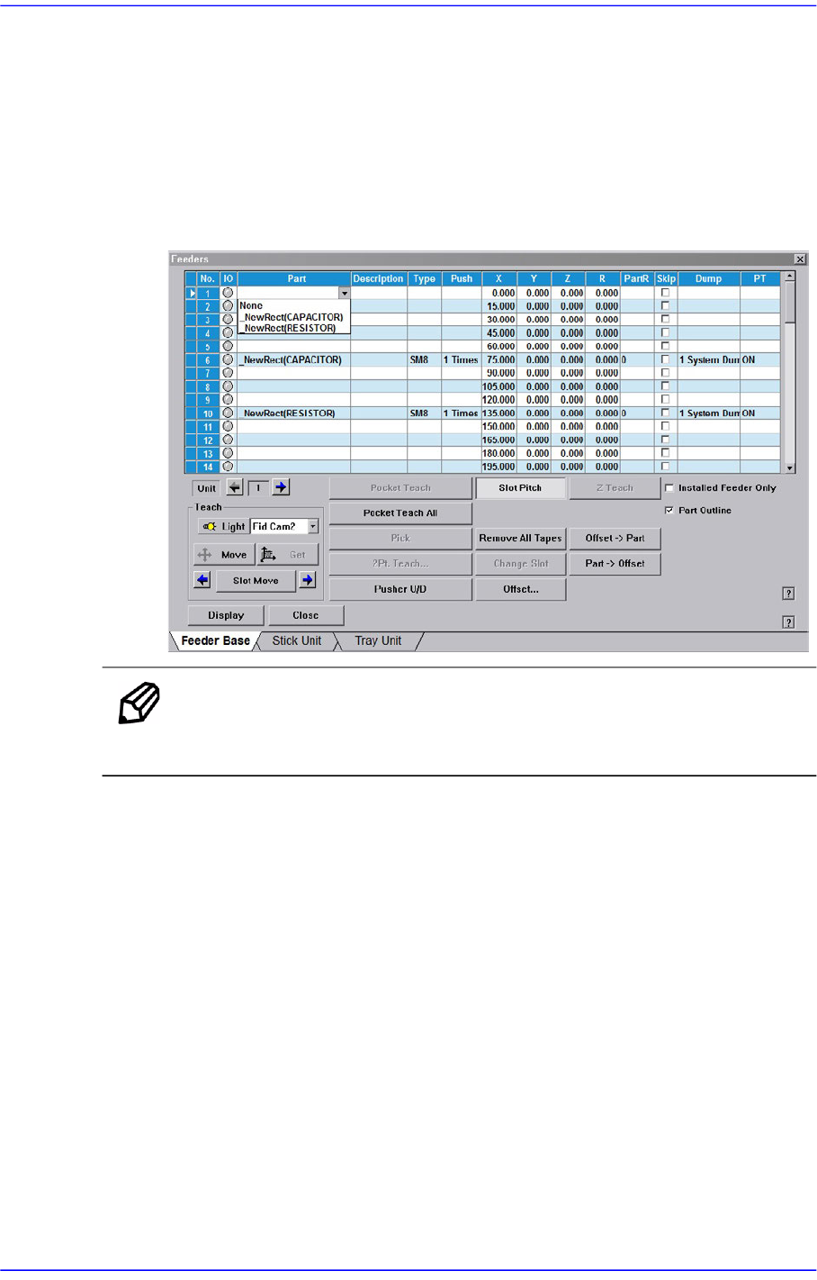
Select the component to install in the corresponding slot. When the <Part> column
is clicked on, the combo box appears, and of the components registered in <1.2
Part>, the list of components to be supplied to “Tape Feeder” is displayed. Select
the component to install in this list. Next is the screen that shows selection of
components in the combo box of <Part> column.
Figure8.2 “Feeder: When the part is selected in the Feeder Base” screen
Memo Changing the part in the selected slot to another part will initialize the
Home Offset value set for the corresponding slot to ‘0’.
<Type> column
Displays the type of the device installed in the corresponding slot. Next screen
shows the content displayed in the <Type> column of the feeder base on which
various devices are installed.