DECAN_S2_Admin(Eng_Ver4.5).pdf - 第260页
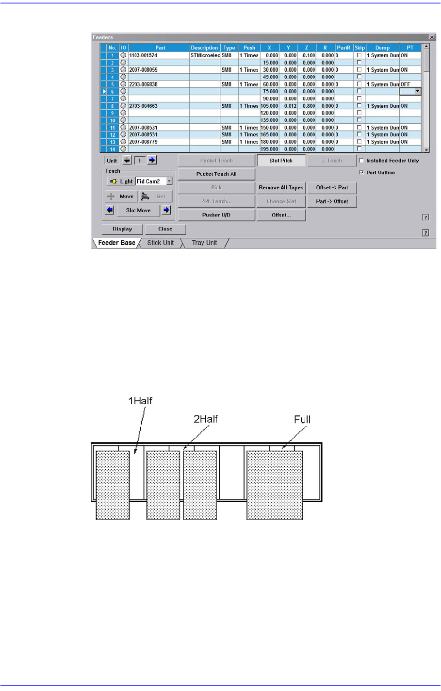
8-3 Feeder Setup Figure8.3 “Feeder: When various devices are installed in the Feeder Base” screen Of the items displayed in the <T ype> column, explanation is given on the following. 1Half: The c orresponding slot …
8-2
Advanced Chip Shooter DECAN S2 Administrator’s Guide
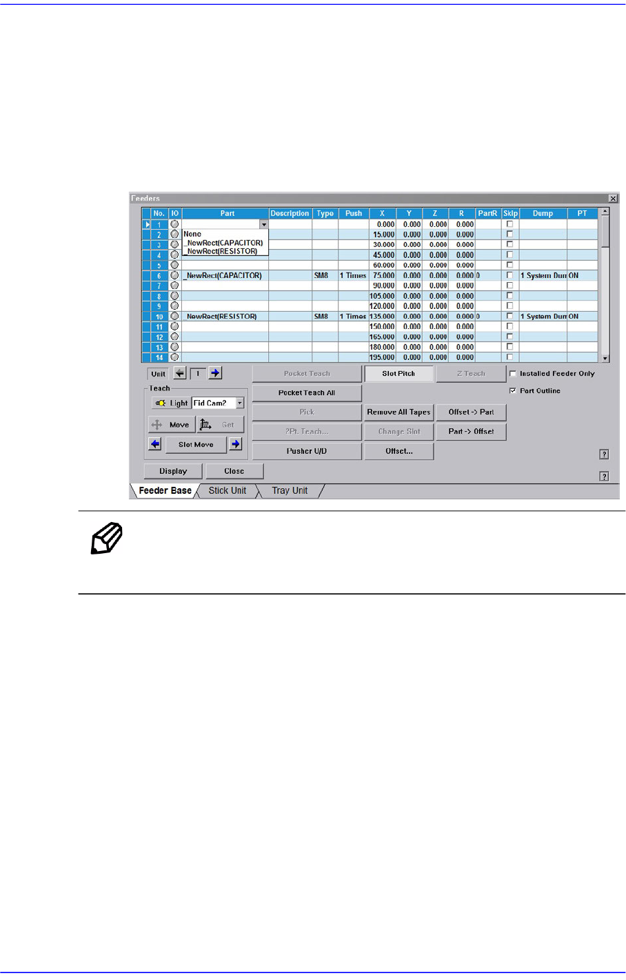
<Part> column
Select the component to install in the corresponding slot. When the <Part> column
is clicked on, the combo box appears, and of the components registered in <1.2
Part>, the list of components to be supplied to “Tape Feeder” is displayed. Select
the component to install in this list. Next is the screen that shows selection of
components in the combo box of <Part> column.
Figure8.2 “Feeder: When the part is selected in the Feeder Base” screen
Memo Changing the part in the selected slot to another part will initialize the
Home Offset value set for the corresponding slot to ‘0’.
<Type> column
Displays the type of the device installed in the corresponding slot. Next screen
shows the content displayed in the <Type> column of the feeder base on which
various devices are installed.
8-3
Feeder Setup
Figure8.3 “Feeder: When various devices are installed in the Feeder Base” screen
Of the items displayed in the <Type> column, explanation is given on the
following.
1Half: The corresponding slot is occupied by 1 device installed in the adjacent
slot.
2Half: The corresponding slot is occupied by 2 devices installed in the adjacent
slot.
Full: The corresponding slot is entirely occupied by the device installed in the
adjacent slot.
<Push> column
When the tape feeder is installed in the corresponding slot, Select the number of
cylinder movements needed to move the part tape forward by 1 pitch.
<X> column
When the tape feeder is installed in the corresponding slot, set the X position to
pick up the component supplied from the tape feeder.
<Y> column
When the tape feeder is installed in the corresponding slot, set the Y position to
8-4
Advanced Chip Shooter DECAN S2 Administrator’s Guide
pick up the component supplied from the tape feeder.
<Z> column
When the tape feeder is installed in the corresponding slot, set the Y position to
pick up the component supplied from the tape feeder.
<R> column
When the tape feeder is installed in the corresponding slot, set the R position
(rotation angle of the head) to pick up the component supplied from the tape
feeder.
Before picking up the part, the head is rotated as much as is set up for part pickup.
For example, when the special rectangular nozzle is used to pick up the connector,
the part can be picked up without problem only when the longitudinal direction of
the nozzle matches with the longitudinal direction of the part.
However, if the nozzle is set up so that the longitudinal section of the nozzle
becomes long and the horizontal section of the part becomes long, the nozzle must
of course be rotated by 90 degrees to pick up the part normally before picking up
the nozzle.
In this case, it is used to set up the rotation angle when picking up the part.
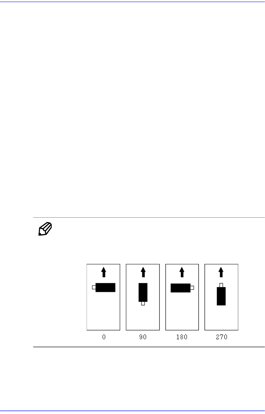
<PartR> column
When the tape feeder is installed in the corresponding slot, set the placement angle
for the component supplied from the tape feeder.
Memo Definition on component supply angle and pick-up angle
Supply angle (In the case of user):
Supply angle (In the case of user):
<Skip> column
When the tape feeder is installed in the corresponding slot, select whether to pick
up the component supplied from the tape feeder or not.
To pick it up leave the check box as it is, and check the check box not to pick it up.