DECAN_S2_Admin(Eng_Ver4.5).pdf - 第276页
8-19 Feeder Setup <Z> edit box Enters the of fse t value. <OK> button Saves the edited contents and clos es the dialog box. <Cancel> button Closes the dialog box without sav ing the edited content…

8-18
Advanced Chip Shooter DECAN S2 Administrator’s Guide
Used for moving the selected object to the assigned position of coordinates by rotating
XY axis driving motor, or for obtaining the present coordinates of the selected object.
<Light> combo box
Setup illumination of fiducial camera to be used for teaching. Please refer to
“7.1.1 Common Align Data” for more information.
combo box
Used for selecting the object to move to the designated coordinates by rotating the
XY axis driving motor or to select the object for which the present coordinates is
searching. Selectable objects are as follows:
Fid Cam2: Select the fiducial camera on the front gantry.
Fid Cam4: Select the fiducial camera on the rear gantry.
Head 1 ~ Head 20: Select #1 ~ #20 heads.
<Move> button
Move the object selected in the combo box to the position of the assigned
coordinates. Before executing <Move> button, the cell in the grid (Coordinates for
pickup point of stick feeder) corresponding to the desired position must be clicked
on.
<Get> button
Obtain coordinates for XY axis with reference to the object selected in the combo
box. At this time, Before executing <Get> button, the cell in the grid (Coordinates
for pickup point of stick feeder) corresponding to the desired position must be
clicked on.
<Pick> button
Picks up parts from the presently selected stick feeder. At this time, the head (Device)
to pickup the part must be selected first. When the pick-up is successful, the following
dialog box is displayed.
Please refer to“8.1.1 Feeder Base” of <Pick> button for more information.
<2Pt. Teach…> button
When teaching the pick-up position of the stick feeder, the center point is calculated
by teaching two corner points at opposite angles of the pocket with the component.
Please refer to “8.1.1 Feeder Base” of <2Pt. Teach…> button for more information.
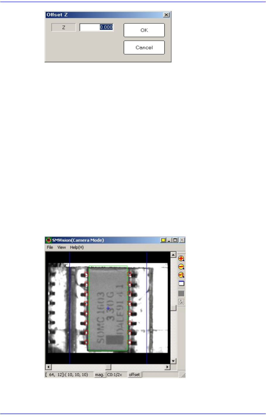
<Offset> button
Applies the offset collective to the Z axis coordinate of the pickup point of the feeder
selected from the <Grid> group.
8-19
Feeder Setup
<Z> edit box
Enters the offset value.
<OK> button
Saves the edited contents and closes the dialog box.
<Cancel> button
Closes the dialog box without saving the edited contents.
<Z Teach> button
Measures the Z axis height for the pickup point of feeder automatically using
pneumatic pressure. Insert the CN040 nozzle into the nozzle holder of the head and
select the tape feeder for which Z axis height is to be measured from the <Grid> group
and then click the <Move> button.
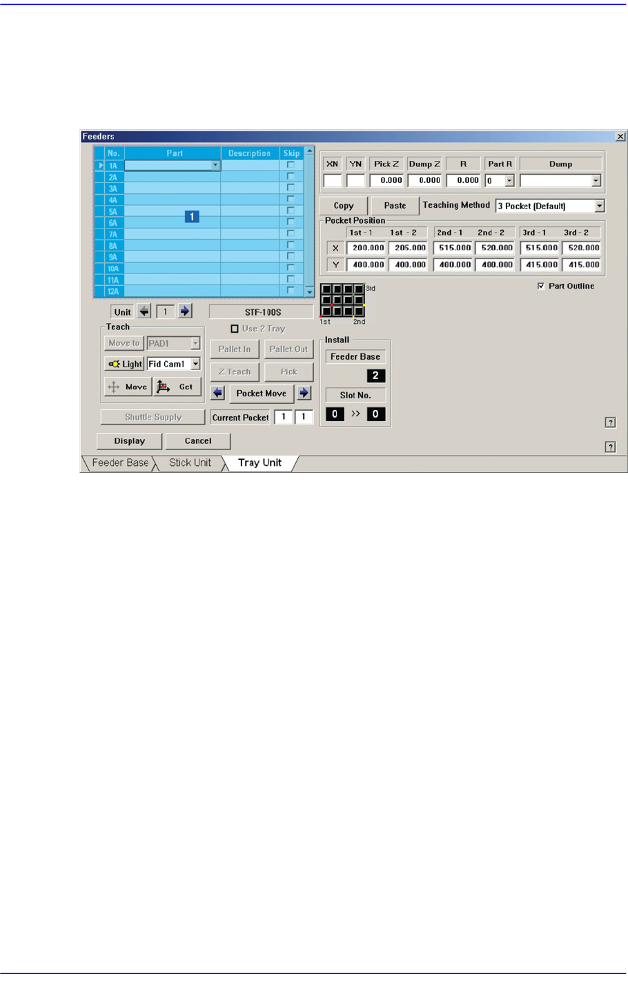
<Part Outline> check box
If this check box is selected, when the fiducial camera is moved to the position of the
corresponding feeder to check the pickup position, the outline image that considers the
angle at which the corresponding part is picked up is displayed on the SMVision
window.
<Display> button
Displays the shape of the feeder that is installed on the feeder base graphically.
8-20
Advanced Chip Shooter DECAN S2 Administrator’s Guide
8.1.3. Tray Unit
Set various data for tray feeders. When “Tray Unit” is selected, the initial screen looks as
follows.
Figure8.6 “Tray Unit” dialog box
1: <Grid> group
<Grid> group
Create and edit data according to the type of the corresponding tray.
<No> column
Refers to the serial number of the tray unit. Basically, “Single” has 10 trays. Each
means one tray.
<Part> column
Select the part to install on the corresponding tray. When the <Part> column is
clicked on, a combo box appears, and among the components registered in <1.2
Part>, a list of components to be supplied to “Tray” are displayed.
Next is the screen that shows component selection in the combo box of <Part>
column.