DECAN_S2_Admin(Eng_Ver4.5).pdf - 第296页
9-5 Step Programming <Use Hot Key> check box Use the hot key to register and mov e the placement point. F2: Move the previous place ment point. F3: Move the next placemen t point. F4: Move the placement poi…
9-4
Advanced Chip Shooter DECAN S2 Administrator’s Guide
<FID> column
If the fiducial mark data of the placement point has been set in <Fiducial…>, “Y”
is displayed, if not “N” is displayed.
<PL> column
Checks the placement point at which placement has already performed. This
equipment provides the function that can select a specific placement point in the
Step dialog box and perform placement at the corresponding point.
If placement is performed by this function, the placement point at which the part
has been placed is automatically check-marked to avoid duplicated placement
when performing placement later.
<LV> column
For parts such as Shield Cap parts, which are to be placed after other parts, this
level value is set to a high value so that corresponding parts can be placed after all
parts with a low level have been placed.
<Teach> group
Used for moving the selected object to the assigned position of coordinates by rotating
XY axis driving motor, or for obtaining the present coordinates of the selected object.
button
Setup illumination level of fiducial camera to be used for teaching installation
position. Please refer to “7.1.1 Common Align Data” for more information.
combo box
Used for selecting the object to move to the designated coordinates by rotating the
XY axis driving motor or to select the object for which the present coordinates is
searching. Selectable objects are as follows;
Fid Cam2: Select the fiducial camera on the front gantry.
Fid Cam4: Select the fiducial camera on the rear gantry.
Head 1 ~ Head 20: Select #1 ~ #20 heads.
<Move> button
Move the object selected in the combo box to the position of the assigned
coordinates. At this time, Before executing <Move> button, the cell in the grid
(Coordinates of installation position) corresponding to the desired position must
be clicked on.
<Get> button
Obtain coordinates for XY axis with reference to the object selected in the combo
box. At this time, Before executing <Get> button, the cell in the grid (Coordinates
of installation position) corresponding to the desired position must be clicked on.
9-5
Step Programming
<Use Hot Key> check box
Use the hot key to register and move the placement point.
F2: Move the previous placement point.
F3: Move the next placement point.
F4: Move the placement point.
F5: Register the placement point.
<Move> group
Moves the head assembly by driving the shaft of the X and Y driving motors to the
placement point of the previous or following row of the current row.
<Move Prev> button
Moves the head assembly by driving the shaft of the X and Y driving motors to the
placement point of the previous row of the current row.
<Move Next> button
Moves the head assembly by driving the shaft of the X and Y driving motors to the
placement point of the following row of the current row.
<Outline> check box
When checking the placement point, it shows pcb pattern image with the virtual
part image in the SMVision window using the Align data.
<Auto> check box
To move continuously, check this check box. When this check box has been
clicked on and <Move Prev> or <Move Next> is clicked on.
<Find> group
Set the string of characters to find. At this time, the column in the grid containing the
string of characters must be specified first.
<Find Prev> button
Finds the string of characters set in the edit box in the previous lines of the current
line of the column specified in the grid.
<Find Next> button
Finds the string of characters set in the edit box in the next lines of the current line
of the column specified in the grid.
<Array> group
<Block> combo box
For block PCB, first select the block to set. Then set other items.
9-6
Advanced Chip Shooter DECAN S2 Administrator’s Guide
Click the button to select the block to set. If it is not a block PCB, it is not
necessary to select the block and the corresponding combo box is disabled.
<Array No.> combo box
Selects an array among the arrays for which placement point is to be indicated.
<Array Extend> check box
Displayed only in the case of Array PCB. Expand the placement point to one PCB
by using the offset value of array PCB.
For example, if the number of current placement points is 10 and the number of
array PCB is 4, then the total number of placement points is expanded to 40.
If it is already expanded, returns to the original status. At this time, all placement
data disappear except for no. 1 array PCB.
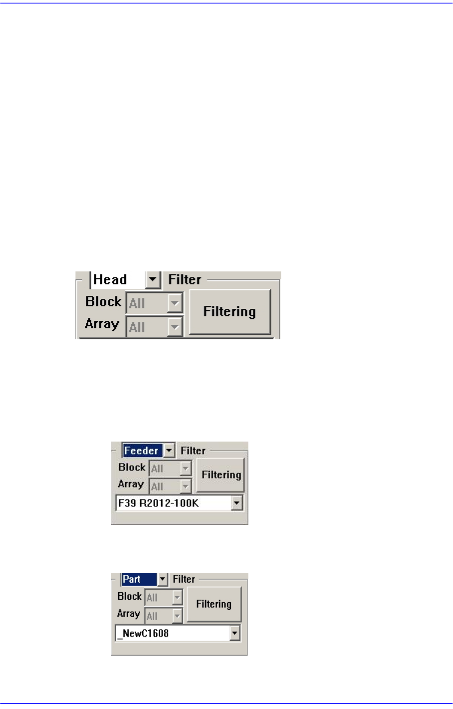
<Filter> Group
Designates the conditions for indicating the placement point shown in the Step dialog
box. Clicking the button will display the filtering function.
<Filter> combo box
Selects the conditions for indicating the placement point. Either ‘Feeder’ or ‘Part’
can be selected. Default is ‘Head’.
When Feeder is selected from the <Filter> combo box
Select the feeder for the part for which the placement point is to be indicated.
When Part is selected from the <Filter> combo box
Select the part for which the placement point is to be indicated.
<Filtering> button