DECAN_S2_Admin(Eng_Ver4.5).pdf - 第379页
14-10 Advanced Chip Shooter DECAN S2 Ad ministra tor’s Guid e 14.2. Camera [F5] Sets various data on the camera. Figure14.6 “C amera Set ting” dialog box <Camer a Select> combo box Select the camera type to set. …

14-9
Machine Calibration
Able to delete the placement offset data of all the heads corresponding to the selected
camera.
<Import Print File> button
Selecting the created Report Viewer Text file by clicking this button will apply the
offset extracted from the CPK Report Viewer to the placement offset of the current
machine.
<Add Offset> group
It is possible to apply X, Y and R placement offsets collectively to all heads.
This function is used at the factory. Users must not apply the offsets at their own
discretion.
<Update> button
Transmits the change data to the equipment and closes the dialog box.
<Cancel> button
Ignores the change data and closes the dialog box.
14-10
Advanced Chip Shooter DECAN S2 Administrator’s Guide
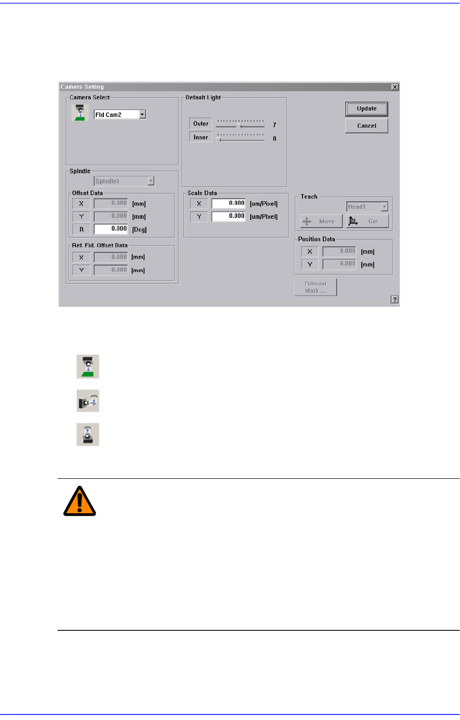
14.2. Camera [F5]
Sets various data on the camera.
Figure14.6 “Camera Setting” dialog box
<Camera Select> combo box
Select the camera type to set. Available camera types are as follows.
Move Camera: Camera used for position teaching or fiducial mark check.
Fly Camera: Camera used for component check, it is attached to each head.
Refers to the camera used to recognize large parts and connectors.
Above screen is the case where the camera type is set to “Fiducial Camera”.
Warning Operation error caused by unauthorized or untrained
personnel or insufficient checking before calibration could
severely damage the equipment or the set up data, or it
could cause personal injury of the operator or the worker
near the equipment. Before carrying out calibration, check
the item to be calibrated and check if there is any worker
near the equipment. And calibration must be carried out by
an authorized and trained user only.
<Scale Data> group
Sets the scale of the camera selected from the <Camera Select> combo box. It can be
set up directly and performing calibration for the camera will input the result value

14-11
Machine Calibration
automatically.
<X> edit box
Set the resolution of the camera in X direction. The unit used is the number of
pixels per mm.
<Y> edit box
Set the resolution of the camera in Y direction. The unit is the number of pixels
per mm.
<R> edit box
Setup the R-axis assembling condition of the camera. The unit is degree.
<Offset Data> group
Sets the camera offset selected from the <Camera Select> combo box. It can be set up
directly and performing calibration for the camera will input the result value
automatically.
<X> edit box
Set the offset value of the camera in X direction between the center of the each
head and center of the camera.
<Y> edit box
Setup the Y-direction offset value of each head center and the camera center.
<R> edit box
Setup the R-direction offset value of each head center and the camera center.
<Default Light> group
Set the default light value. Please refer to “7.1.1 Common Align Data”for more
information.
<Position Data> group
Set the position of the fix camera.
<X> edit box
Set the X position value of the fix camera.
<Y> edit box
Set the Y position value of the fix camera.
<Ref. Fid. Offset Data> group
Each head has its own reference fiducial mark, which is used to correct the offset.
<Teach> group
Set the position offset of the fix camera.
combo box
Used for moving the selected object to the position of fix camera by rotating XY