DECAN_S2_Admin(Eng_Ver4.5).pdf - 第418页
14-49 Machine Calibration 7. If t he calibration procedure i s completed prope rly , the result as shown in the following figure is d ispl ayed and then the m e ssage, “Next, Remove the Calibration Noz zle from Head1. Cl…
14-48
Advanced Chip Shooter DECAN S2 Administrator’s Guide
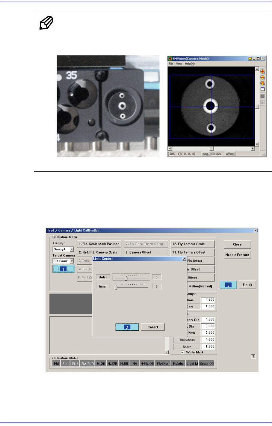
Memo Place the calibration tool at the calibration tool position on the ANC
by referring to the following figure.
5. Then the message “Calibration is Prepared. To Calibrate, Click [Next]” appears in the
message window. At this time, click the <Light…> button and adjust the brightness of
the light in the ‘Light Control’ dialog box so that the fiducial mark on the calibration
tool that is seen in the ‘SMVision’ window can be seen clearly. Then click the <Next>
button.
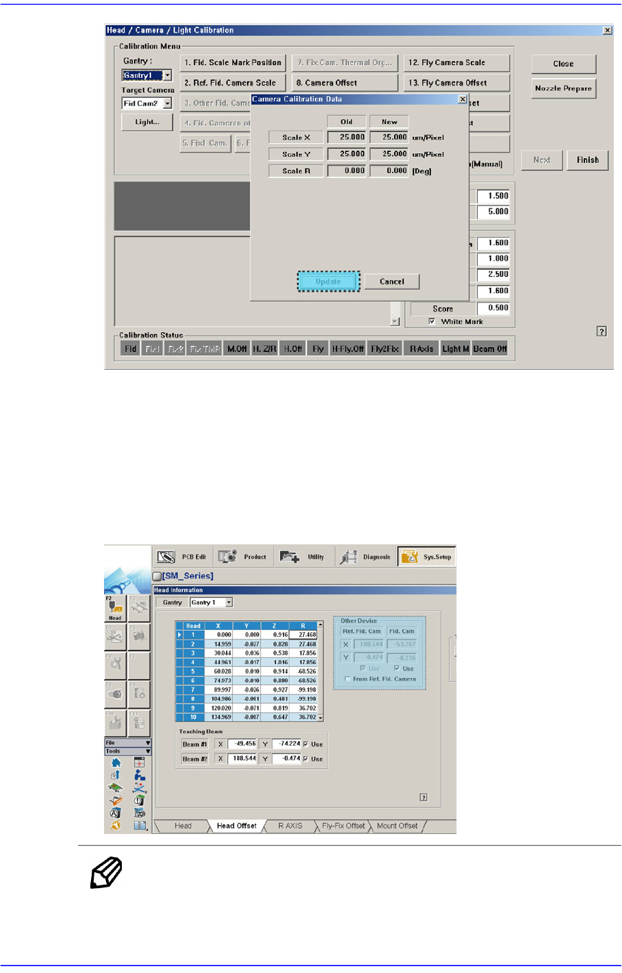
6. The calibration is performed automatically. If it is completed, the calibration result is
displayed as shown in the following figure. Click the <Update> button to apply the
new calibration value.
14-49
Machine Calibration
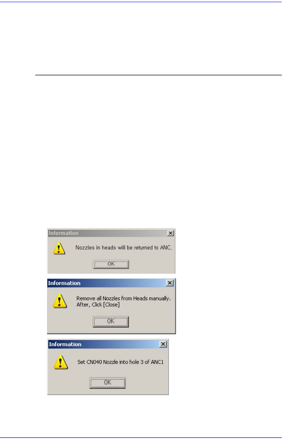
7. If the calibration procedure is completed properly, the result as shown in the following
figure is displayed and then the message, “Next, Remove the Calibration Nozzle from
Head1. Click [Next] for Moving Down Head. After Moving, Remove the Nozzle
Manually.”
Click the <Next> button to remove the nozzle inserted into the nozzle holder of Head
1 manually. Then remove the calibration tool on the ANC.
The measurement result can be confirmed in the Head Offset dialog box.
Memo The reference values for the calibration of the Fiducial Camera Offset
(FOV 7.5) is as follows.
Gantry1
14-50
Advanced Chip Shooter DECAN S2 Administrator’s Guide
Offset X : -189.5 ~ -187.5 (mm)
Offset Y : -1 ~ 1 (mm)
Gantry2
Offset X : 187.5 ~ 189.5 (mm)mm
Offset Y : -1 ~ 1 (mm)
14.3.10.2. Head Z / R Offset Calibration
The distance from the upper surface of the PCB to the Z axis home is set mechanically. For
the Z offset calibration, measure the offset for this distance based on the upper surface of
the PCB by using pneumatic pressure.
For the R offset calibration, measure the offset of the angle to align the nozzle holder
based on zero (0) degrees.
The following is the process that the Z offset calibration is performed. The nozzle used for
calibration is the CN040 nozzle.
1. Click the <Nozzle Prepare> button and remove all nozzles inserted in the nozzle
holders of all heads. Insert the CN040 nozzle into the No. 3 hole of the ANC.
For Gantry 1, insert the CN040 nozzle into the No. 3 hole of the front ANC. For
Gantry 2, insert it into the No. 3 hole of the rear ANC.
Since the position at which the Z offset is measured deviates from the calibration tool
position (center) by 3mm, if any foreign material on the calibration tool is present,
remove it.