DECAN_S2_Admin(Eng_Ver4.5).pdf - 第424页
14-55 Machine Calibration 8. Perform the calibratio n form Head 2 to Head 10 in the same manner . 9. Click the <Updat e> button to apply the calibration result to the machine. 14.3.10.3. Light [F8] Calibrate the br…
14-54
Advanced Chip Shooter DECAN S2 Administrator’s Guide
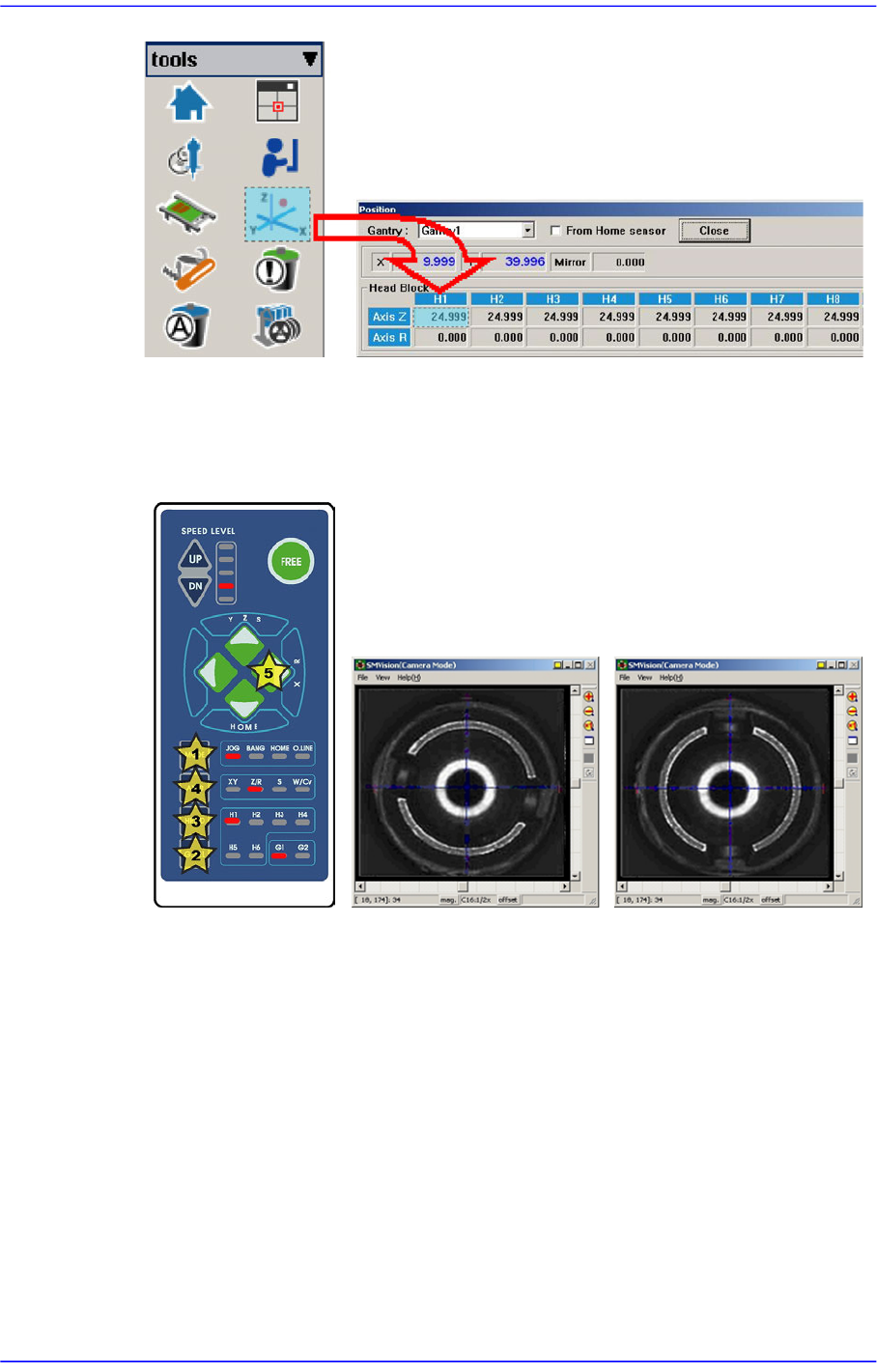
6. Rotate the spindle in the R-direction by using the teaching box so that the shape of the
nozzle holder becomes ‘( )’. At this time, the nozzle holders of the heads with
interlocked mechanism must be assembled in the same direction.
That is, the mechanisms of the #1~#2 heads and #3~#4 heads, #5~#6 heads, #7~#8
heads, #9~#10 heads must be assembled first in the same direction by using the jig for
a nozzle holder.
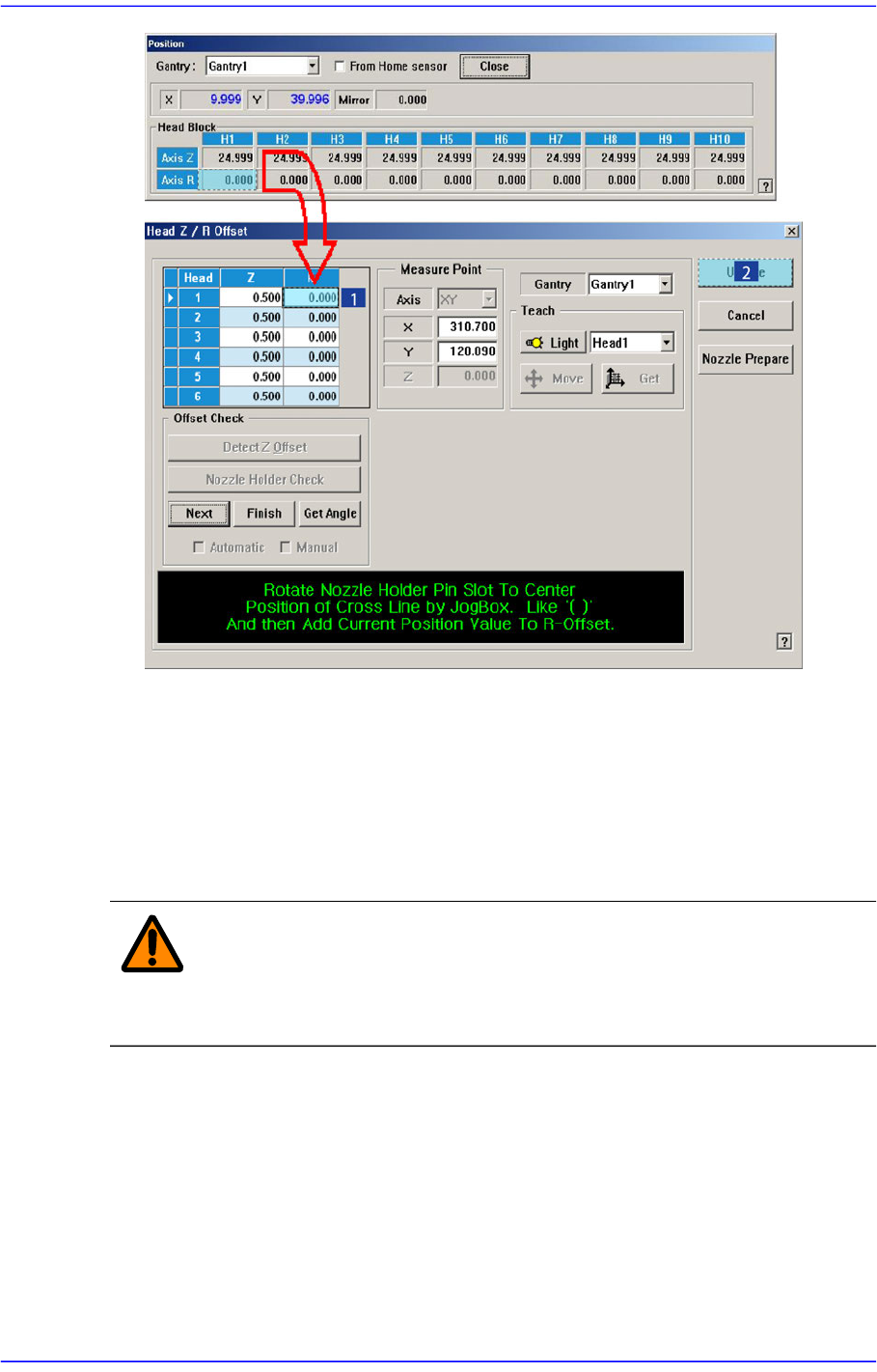
7. At this time, input the current position value of the R-axis and click the <Update>
button.
14-55
Machine Calibration
8. Perform the calibration form Head 2 to Head 10 in the same manner.
9. Click the <Update> button to apply the calibration result to the machine.
14.3.10.3. Light [F8]
Calibrate the brightness of the illumination for the fly camera and fix camera. For more
information please refer to “14.4. Light Mapping”.
Caution Since the nozzle for the SM32x model is not compatible to
the one for the light mapping used for the SM32x model, do
not use it for this machine.
14-56
Advanced Chip Shooter DECAN S2 Administrator’s Guide
14.3.10.4. Head Offset Calibration
Measure the distance (XY Offset) between the center of the gantry fiducial camera and the
center of each head.
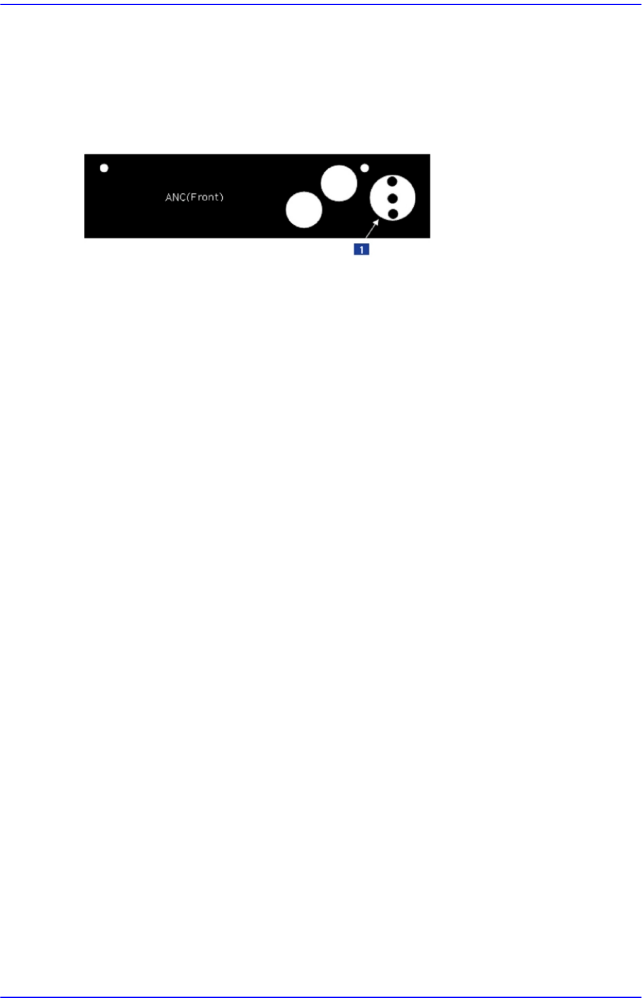
In order to perform calibration of the XY offset of each head, first check if the calibration
tool is placed on the calibration tool position of the front ANC.
1: Calibration Tool Position
The following is the procedure to calibrate the XY offset of the head;
1. Click the <Nozzle Prepare> button and insert the CN400 nozzle into the No. 1 hole of
the ANC manually.
2. If the <9. Head Offset> is clicked after selecting the <Automatic Next> check box,
calibration is performed for the selected gantry automatically.
If calibration is performed after selecting the <No Real Motion [Manual]> check box,
the nozzle is inserted into each head manually. Click the <Next> button to move onto
the next step.
If calibration is performed without selecting either the <Automatic Next> check box
or < No Real Motion [Manual]> check box, the nozzle is changed automatically for
the currently selected nozzle. Click the <Next> button to move onto the next step.
If the <9. Head Offset> button is clicked, the message “First, We must Put all Nozzles
From Heads Manually. To Moving Down Z Axis, Click [Next]” appears in the
message box. Click the <Next> button to move down the Z axis of the head in order to
remove all nozzles inserted in the nozzle-holder manually.