DECAN_S2_Admin(Eng_Ver4.5).pdf - 第467页
15-16 Advanced Chip Shooter DECAN S2 Admi nistra t or’s Guide <Update> button T ransmits the change data to the equipment and closes the dialog box. <Cancel> button Ignores the change data and closes the …
15-15
System Setup
Determines whether to use the dump conveyor. D This check box must be selected
to set the dump conveyor related items.
<User Defined Dump box> group
Setup the data related with the ‘User Dump Box’ installed by the user. The maximum
number of ‘User Dump Box’ able to be installed by the user is 8.
‘User Dump Box’ is utilized for dumping parts in the ‘User Dump’ position when
dumped parts are expensive, or require classification, or parts error has occurred in a
box installed in the equipment by the user.
Memo “System default Dump Box” is assigned as the default box when
‘Dump’ item of the feeder supplying the corresponding part in the
feeder dialog box is not assigned after setting up the ‘User Dump
Box’.
Method of setting up the ‘User Dump Box’ is as follows;
1. Select <Use> check box and move the head to the position where the ‘User Dump
Box’ is installed using the ‘Teaching Box’.
2. Select ‘Fid Cam’ in the <Teach> area, and fit the center of the ‘User Dump Box’
to the center of cross lines of the ‘Fiducial Camera’ seen on the SMVision
monitor.
3. Select the corresponding cell in the <User Defined Dump box> group with the
mouse, and Input the value of the present coordinates by clicking on the <Get>
button.
4. Click on the <Update> button to reflect the changed value.
After updating, select ‘User Dump’ of the feeder supplying parts using ‘User
Dump’ in the feeder dialog box.
<User defined Dump Box - No> column
Indicates the number of ‘User Dump Box’.
< User defined Dump Box - Use> column
Setup whether to use the corresponding ‘User Dump Box’ or not.
< User defined Dump Box - X> column
Setup the X position of the corresponding ‘User Dump Box’.
< User defined Dump Box - Y> column
Setup the Y position of the corresponding ‘User Dump Box’.
< User defined Dump Box –Release Z> column
Setup the height of the head Z-axis while dumping in the corresponding ‘User
Dump Box’.

15-16
Advanced Chip Shooter DECAN S2 Administrator’s Guide
<Update> button
Transmits the change data to the equipment and closes the dialog box.
<Cancel> button
Ignores the change data and closes the dialog box.
15-17
System Setup
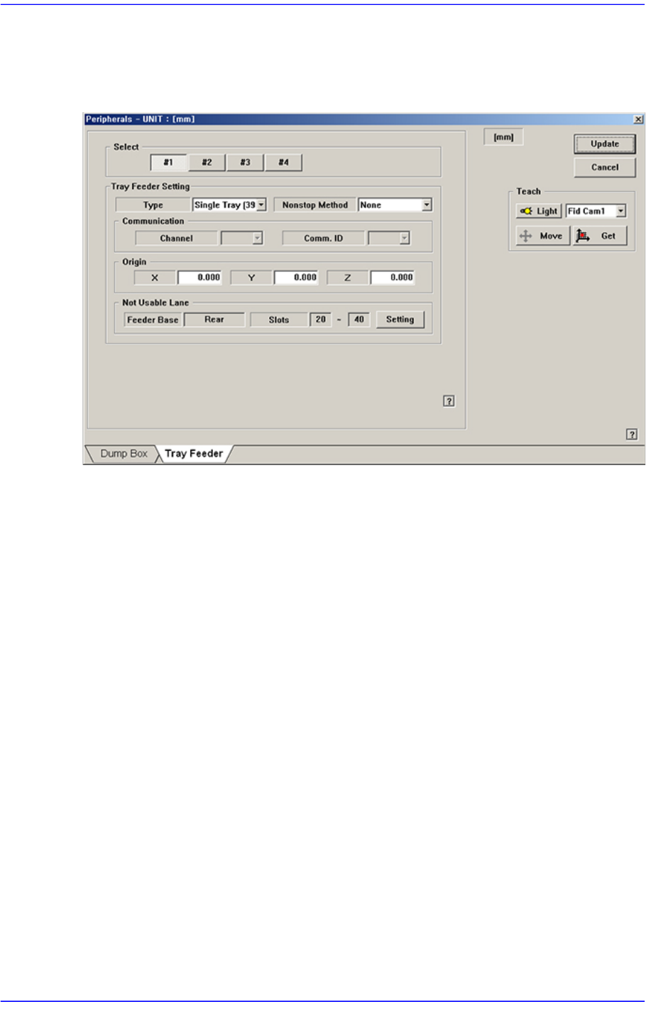
15.3.2. <Tray Feeder> Tab dialog
Sets the tray feeder related data. Selecting this button will display following dialog box.
Figure15.8 “Accessory” dialog box “Tray Feeder” Tab dialog
<Select> option button
Selects the tray feeder unit. Available tray feeder units are No. 1 to No.4 tray feeder
units.
That is, a total of 4 tray feeders can be installed. (Maximum 2 trays can be installed for
the type of trays that can communicate with the equipment.)
<Tray Feeder Setting> group
Selects the type of the set tray feeder unit. Available type is as follows.
<Type> combo box
Selects the type of the set tray feeder unit. Available type is as follows:
NONE: Means that no tray is installed.
Single Tray[39321]: Refers to the tray installed on the feeder base.
<Nonstop Method> combo box
Determines whether to use the non-stop function.
Note: The nonstop function is not used.
Master/Slave: One rack is used as master and another rack is used as slave.
Master/Master: One rack is used until the parts are exhausted, and then
another rack is used.
<Communication> group