DECAN_S2_Admin(Eng_Ver4.5).pdf - 第475页
15-24 Advanced Chip Shooter DECAN S2 Admi nistra t or’s Guide 3. After selecting the camera for which light mapping is to be performed in the <Select Camera> gr oup, click the <Mapping/T est> button. 4. Click…
15-23
System Setup
<Test> button
Perform test for the mapping result. The light level that does not satisfy the
reference value is searched automatically and it is displayed in the result file.
Perform mapping with the <Refine Mapping Result> check box being selected.
State display
Displays current progressing state.
Camera (Number of camera for which test or mapping is completed) /(Total
number of selected camera)
(I: Inner Level, O: Outer Level, S: Side Level, B: Back Level)
<Close> button
Closes the dialog box.
<Update> button
Transmits the set data to the equipment and closes the dialog box.
<Cancel> button
Ignores the set data and closes the dialog box.
Perform light mapping of the Fly Camera in the following manner:
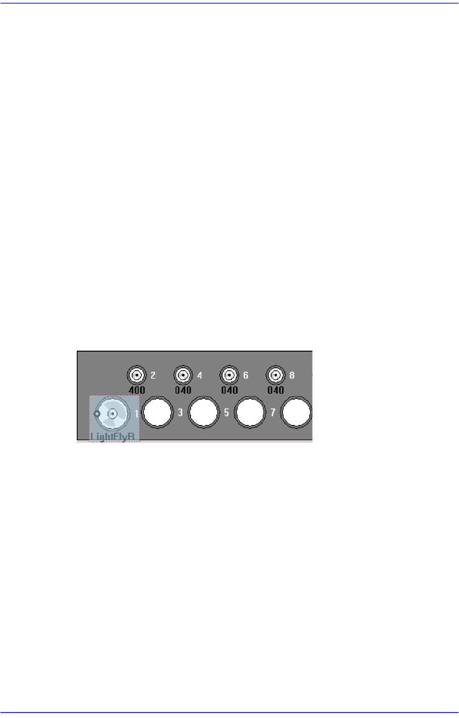
1. Place the light mapping tool in the No. 1 hole of the ANC.
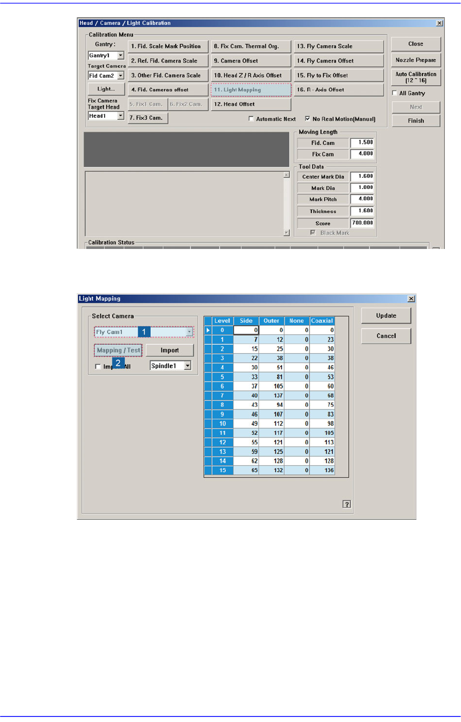
2. Click the <Light Mapping> button to execute the light mapping dialog box.
15-24
Advanced Chip Shooter DECAN S2 Administrator’s Guide
3. After selecting the camera for which light mapping is to be performed in the <Select
Camera> group, click the <Mapping/Test> button.
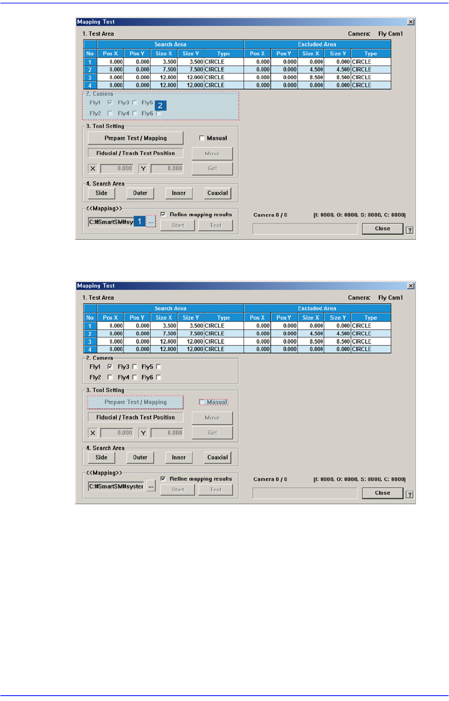
4. Click the <...> button in the <<Mapping>> group to select the file for calibration.
Then select the camera to be calibrated in the <2. Camera> group.
15-25
System Setup
5. After unchecking the <Manual>check box in the <3. Tool Setting> group, click the
<Prepare Test / Mapping> button.