DECAN_S2_Admin(Eng_Ver4.5).pdf - 第510页
15-59 System Setup <Machine/ BCR> group <Machine No.> combo box Sets the ID so that the MES host may recognize the machine. <Configure BCR...> button Clicking this button will display t he dialog …
15-58
Advanced Chip Shooter DECAN S2 Administrator’s Guide
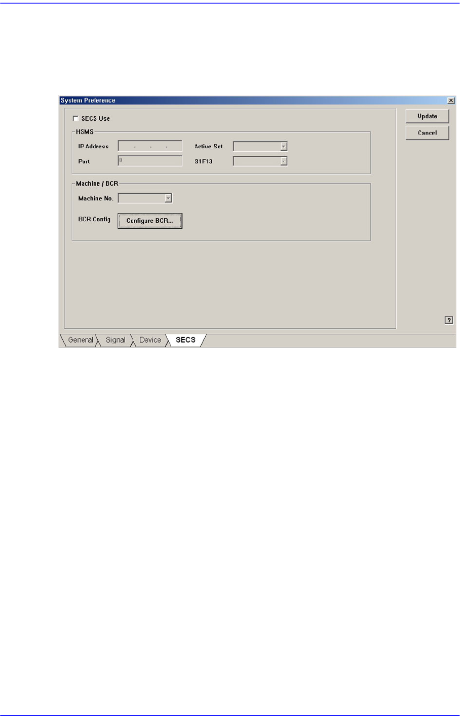
15.5.4. <SECS> tab dialog
Set the communication with the MES host. This function is selected when using the
gamma interface applied by Samsung Electronics.
Figure15.20 “SECS” tab dialog
<SECS Use> check box
Select this check box to perform setup for communication with the MES host.
<HSMS> group
<IP Address> edit box
Inputs the IP address assigned to the machine.
<Active Set> combo box
Sets one of the items first to which the connection command will be transmitted
for communication between the MES host and the machine.
Active: Attempts to connect the TCP/IP protocol to the host from the machine.
Passive: Attempts to connect the TCP/IP protocol to the machine from the
host.
<Port> edit box
Input the port assigned for communication between the MES host and the
machine.
<S1F13> combo box
Equipment: Attempts to connect the HSMS protocol to the host from the
machine.
Host: Attempts to connect the HSMS protocol to the machine from the host.
15-59
System Setup
<Machine/ BCR> group
<Machine No.> combo box
Sets the ID so that the MES host may recognize the machine.
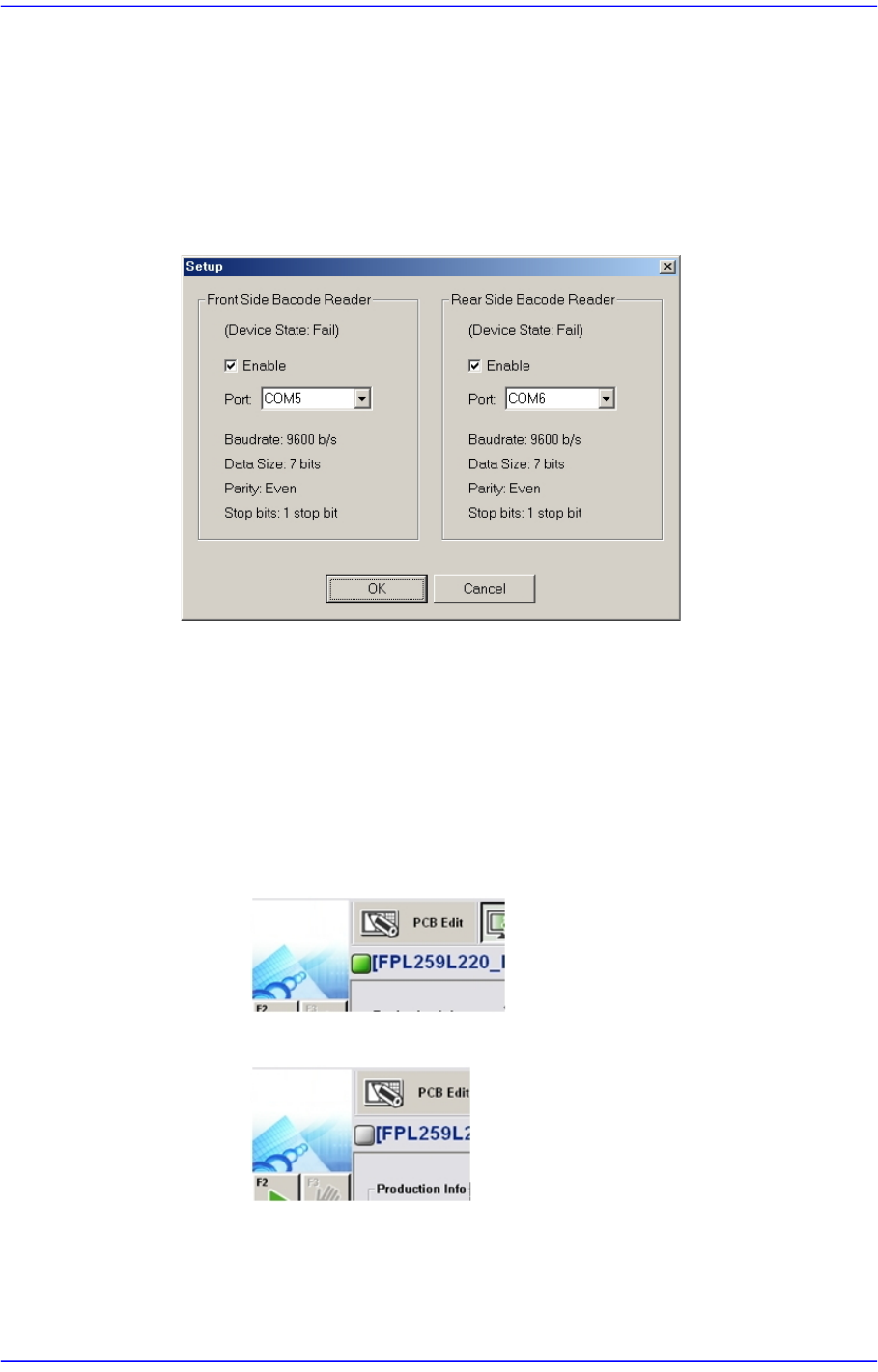
<Configure BCR...> button
Clicking this button will display the dialog box for the barcode scanner setup as
follows.
<Enable> check box
Select this check box to use the barcode reader.
<Port> combo box
Sets the port for communication between the machine and the barcode
scanner.
Check the connection status between the MES host and the machine.
When they are connected
When they are not connected
15-60
Advanced Chip Shooter DECAN S2 Administrator’s Guide
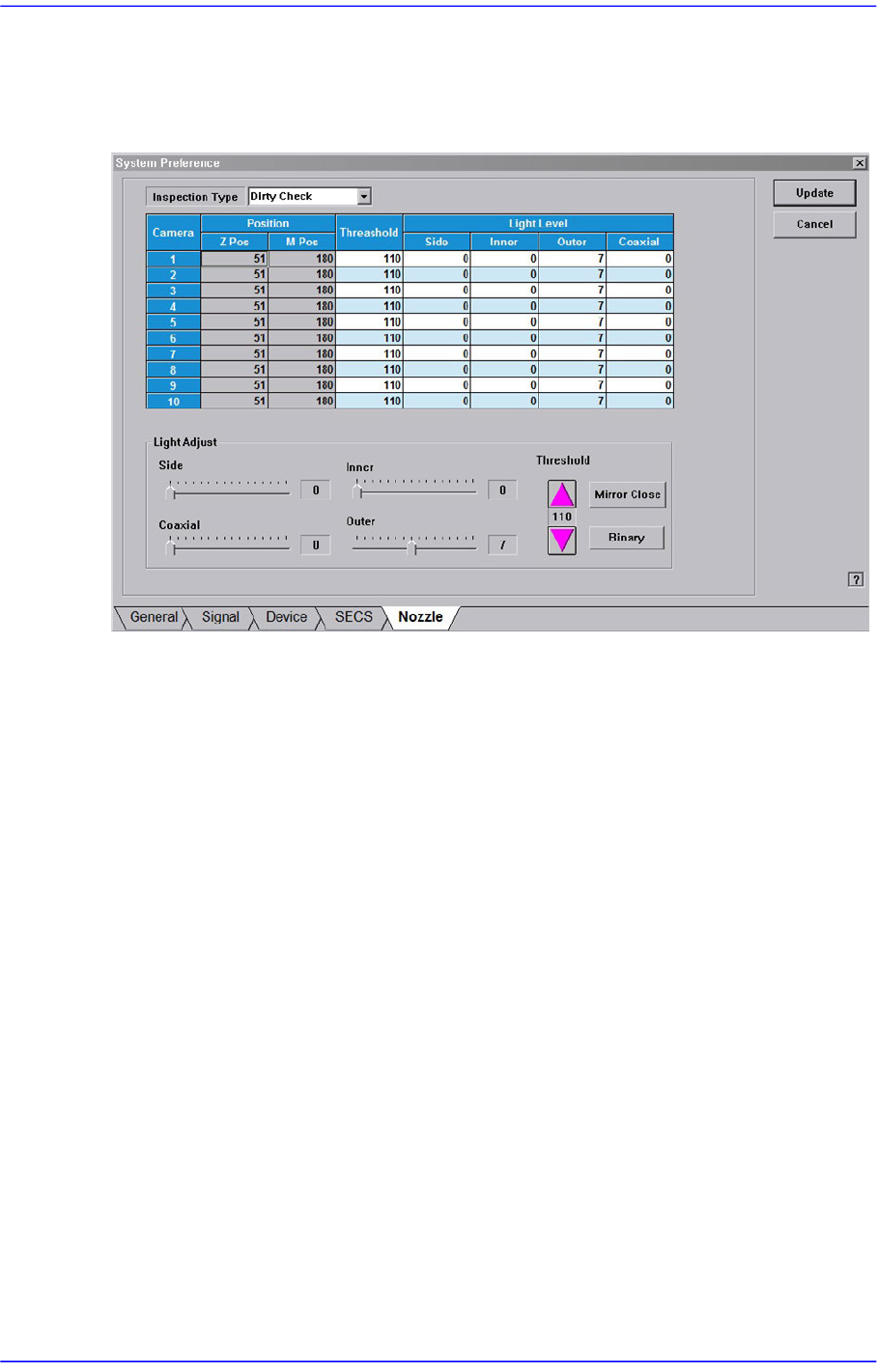
15.5.5. <Nozzle> tab dialog
Sets the parameter of the fly camera when checking for the contamination of a nozzle tip.
Figure15.21 “Nozzle” Tap dialog
<Inspection Type> combo box
Sets the parameter of the fly camera when checking for the contamination of a nozzle
tip.
Dirty Check
The parameters of the fly camera used to test whether the nozzle tip is polluted are
displayed on the screen.
Tip Check
The parameters of the fly camera used to test whether the nozzle tip is present are
displayed on the screen.
Holder Check
The parameters of the fly camera used to test the nozzle holder are displayed on
the screen.
<Position> group
Z-Pos
Indicates the Z-axis height from the upper surface of the PCB to the nozzle tip
end.
M-Pos
Indicates the rotation angle of the mirror for the fly camera.
<Threshold> column