2OM-1751-003w_G5S - 第344页
2OM-1751 6-72 F2F67 (2) Conrm that the component is in the yellow circle (frame). When it is in the circle, press the [Y es] button. Otherwise, press the [No] button. F2F68 1303-001 7.3 "COMP RCG" T est Window
2OM-1751
6-71
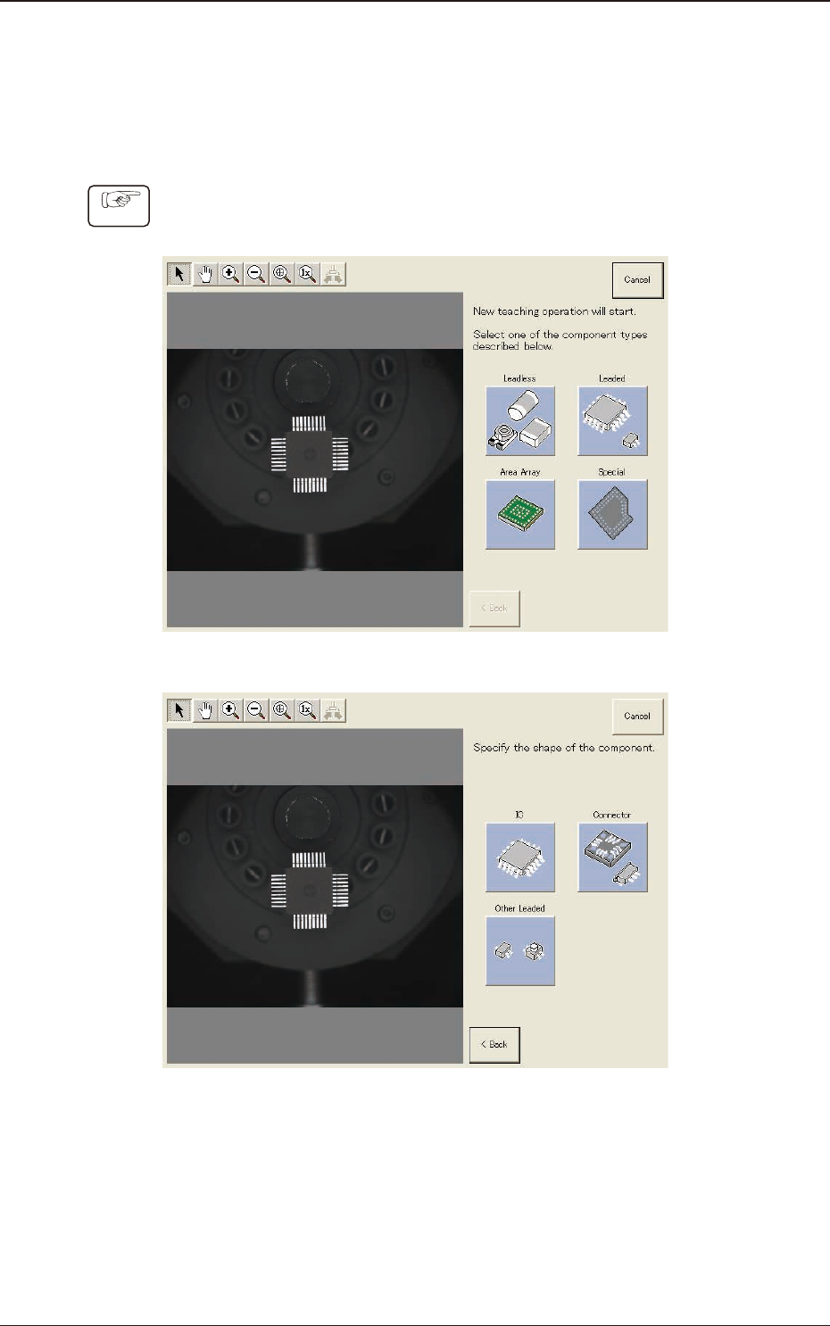
7.3.7 "Create Teach" Wizard
Follow the steps below to newly create data to be taught.
7.3.7.1 Leaded Components - QFP
Procedure
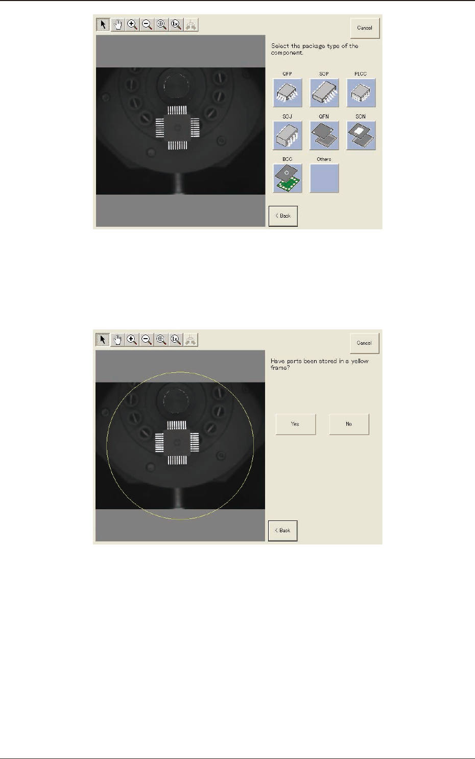
(1) Select [Leaded], [IC] and [QFP] in this order.
F2F65
F2F66
1303-001
7.3 "COMP RCG" Test Window
2OM-1751
6-72
F2F67
(2) Conrm that the component is in the yellow circle (frame).
When it is in the circle, press the [Yes] button. Otherwise, press the [No]
button.
F2F68
1303-001
7.3 "COMP RCG" Test Window
2OM-1751
6-73
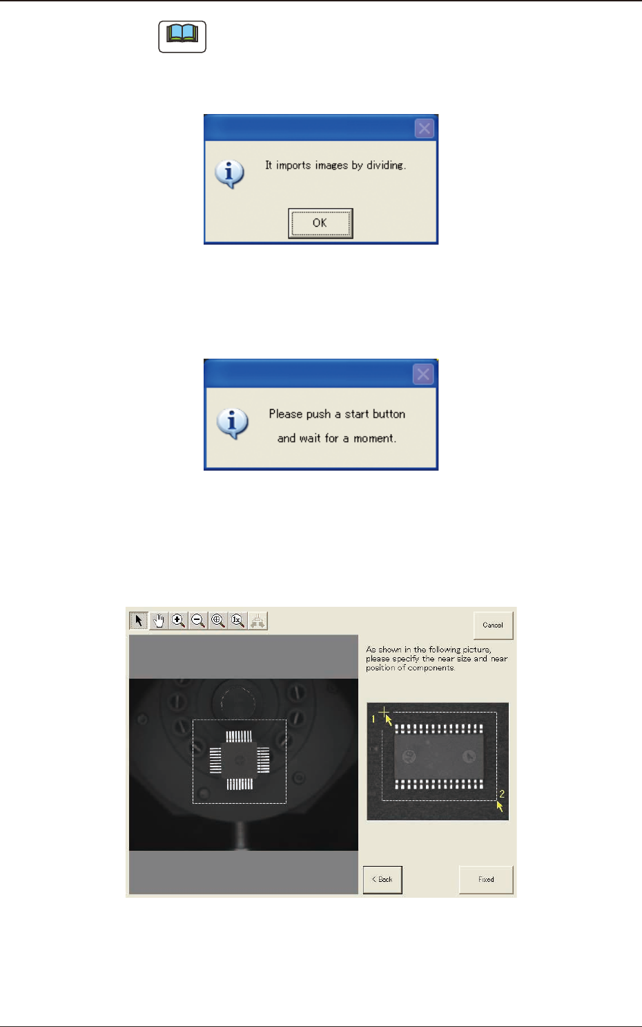
Note
When the [No] button is selected, the component image is split into several
parts which are subsequently captured and reassembled to create the whole
image to be displayed.
The following dialog box appears. Press the [OK] button.
F2F69
When the [OK] button is pressed, the following dialog window opens.
Press the [START] button on the operation panel and wait until the divided
image capturing is completed.
F2F70
(3) After clicking the upper left of the component image, click the lower right to
place the whole component image within a frame.
(Specify an approximate size and position of the component.)
F2F71
1303-001
7.3 "COMP RCG" Test Window