2OM-1751-003w_G5S.pdf - 第105页
2OM-1751 1-53 1303-001 4.2.8 Splicing When the [Splicing] button is pressed on the "Opr.Mode" tab sheet, the following window appears. [3] [2] [1] [4] F2A35 [1] Splicing tape length The splicing tape length is …

2OM-1751
1-521303-001
4.2 "Opr.Mode" Tab Sheet
[14] Poclet recog condition when restarting
The conditions for pocket recognition when the machine operation is re-
stared, are setup in this section.
Function Setting
"Enable" or "Disable" is selected for the pocket recognition condition in the
re-start operation, in this selection box.
Start condition
The time period from the machine stop (standby, stop or pause) mode to
machine operation start mode, is setup in this data box.
Recog Interval at Joint
The intervals for the automatic teaching to be performed periodically for the
feeder pocket recognition based on the number of tape feeding times when
the machine operation is re-started, are setup in this data box.
End condition (Interval)
The number of tape feeding times until the pocket recognition end, is setup
in this data box.
2OM-1751
1-531303-001
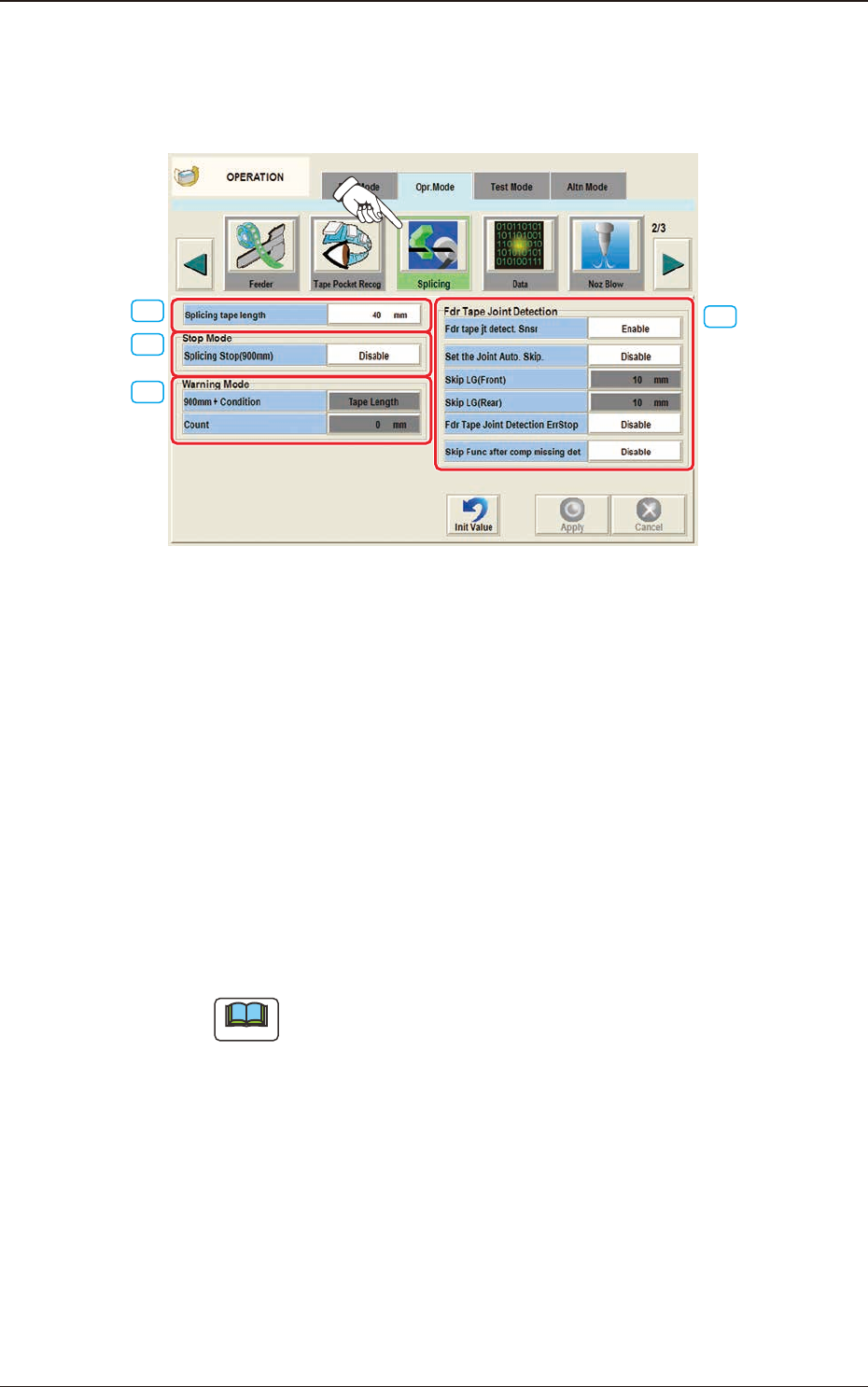
4.2.8 Splicing
When the [Splicing] button is pressed on the "Opr.Mode" tab sheet, the following
window appears.
[3]
[2]
[1]
[4]
F2A35
[1] Splicing tape length
The splicing tape length is set in this text box.
[2] "Stop Mode" Group Box
Splicing Stop (900 mm)
The [Enable] or the [Disable] button can be selected to determine whether or
not the machine should be stopped for tape splicing required when the length
of the remaining tape becomes shorter than 900 mm.
[3] "Warning Mode " Group Box
The following conditions can be added to the criterion (Length of Remaining
Tape: 900 mm) to set the time to issue a warning of splicing need.
Note
It cannot be specied to issue a splicing warning message with the length
of the remaining tape shorter than 900 mm.
900 mm + Condition
The condition for displaying the alarm for splicing, is selected from the
following items.
4.2 "Opr.Mode" Tab Sheet

2OM-1751
1-541303-001
Tape Length
The condition for displaying the alarm for splicing, is set based on the
remaining tape length.
PCB Count
The condition for displaying the alarm for splicing, is set based on the
number of producible PCBs.
[Count] Button
When this button is pressed, it becomes possible to set the number of PCBs
(PCBs that can be produced) as a condition to issue a splicing warning
message.
[4] "Fdr Tape Joint Detection" Group Box
Fdr tape jt detect. Snsr
"Enable" or "Disable" is selected for the joint seam detection sensor.
Set the joint Auto. Skip.
"Enable" or "Disable" is selected for the "Set the joint Auto. Skip", in this
text box.
Skip LG(Front)
The skip start position from the joint is set in this text box.
Skip LG(Rear)
The skip end position from the joint is set in this text box.
Frd Tape Joint Detection ErrStop
When an error (E3) is caused in the tape feeder, the machine is stopped.
Reference
Refer to "SIGMA-G4/G5 Tape Feeder Instruction Manual" for the derails
of the error codes for the tape feeder.
Skip Func after comp missing det
"Enable" or "Disable" for the Skip after "No Component" detected, is
selected in this selection box.
4.2 "Opr.Mode" Tab Sheet