2OM-1751-003w_G5S.pdf - 第134页
2OM-1751 2-12 3. Explanation of Pattern Program In this instruction manual, the placement coordinate reference is based on "Front Right". 3.1 Common SET Note This data is used in the dual transfer operation (op…

2OM-1751
2-111303-001
2.7 Composition of Placement Data
The set parameters are used to place the components (IDs in the placement feeder
location data) on the points with the specied coordinates in the designated
direction.
One step is allocated for each component to be placed.
Reference
Refer to "3.7 Placement Data" for the details of each item.
Items Ref. No.
Un (G01)
Offset Data (G02)
Offset (G02)
Unit Control (G02_01)
Offset
X [mm], Y [mm], Z [ ° ], H [mm]
(G02_02)
Unit PCB Fiducial (G02_03)
Recog Coord
X1, Y1, X2, Y2
(G02_04)
Fiducial Mark
FM1, FM2
(G02_05)
D-Data (G03)
P-Data (G03)
PNo. (G03_01)
X [mm], Y[mm] (G03_02)
Z [ ° ] (G03_03)
H [mm] (G03_04)
Component ID (G03_05)
Fdr. No. (G03_06)
Symbol (G03_07)
C (G03_08)
Comment (G03_09)
ADJ X,Y (G03_10)
O-Data (G04)
Ono. (G04_01)
X [mm], Y[mm] (G04_02)
Z [ ° ] (G04_03)
H [mm] (G04_04)
C (G04_05)
Comment (G04_06)
B-X, B-Y (G04_07)
T2B15
2.7 Composition of Placement Data

2OM-1751
2-12
3. Explanation of Pattern Program
In this instruction manual, the placement coordinate reference is based on "Front
Right".
3.1 Common SET
Note
This data is used in the dual transfer operation (option).
1303-001
3. Explanation of Pattern Program
2OM-1751
2-13
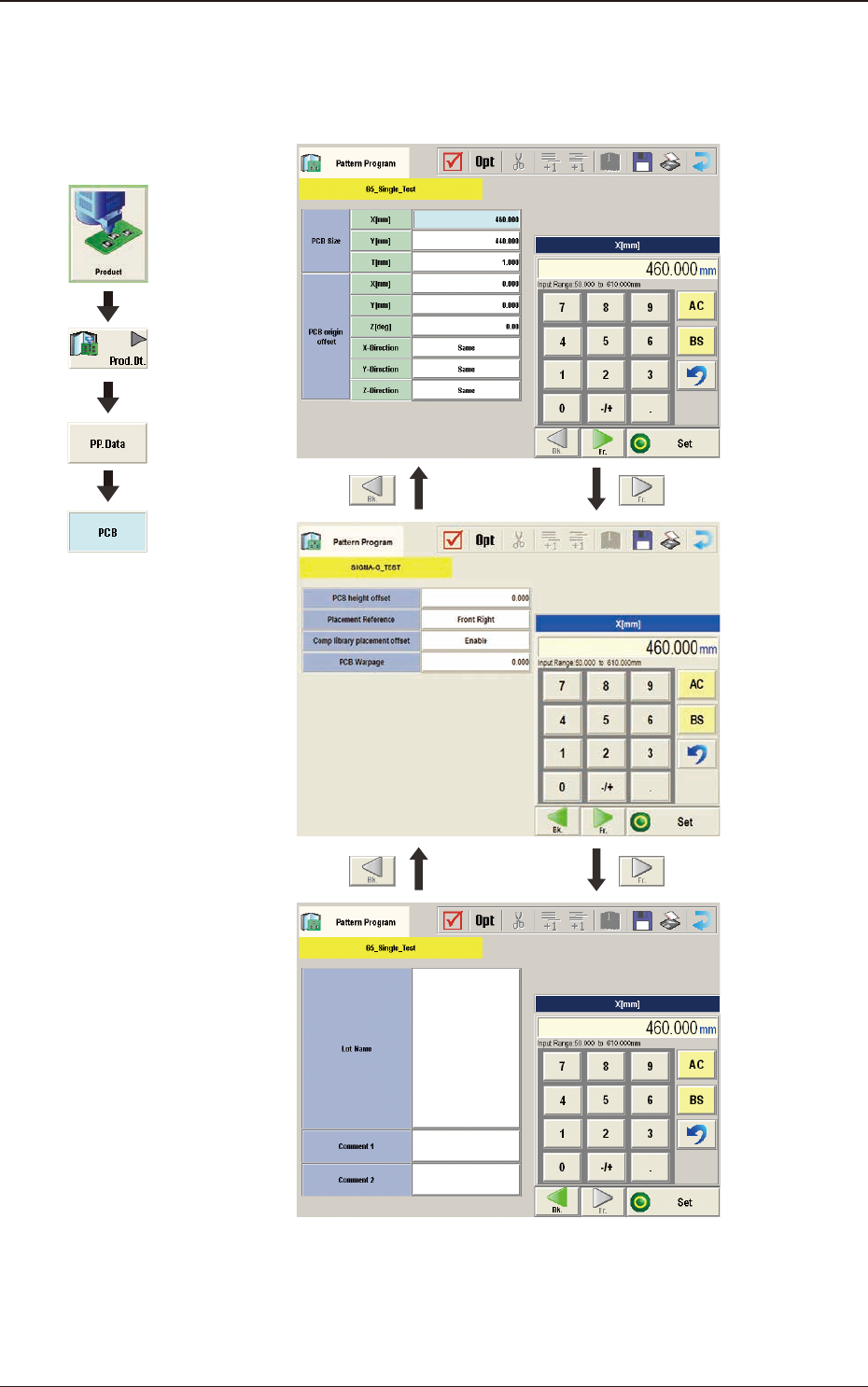
3.2 PCB
(B01) PCB Data
F2B3
1303-001
Graphic
Development
3.2 PCB