2OM-1751-003w_G5S.pdf - 第139页
2OM-1751 2-17 1303-001 (B01_03) PCB height offset [mm] Set an offset value as a nozzle descending distance based on the upper surface of the PCB in the component placement section. This offset value applies to all compon…
2OM-1751
2-161303-001
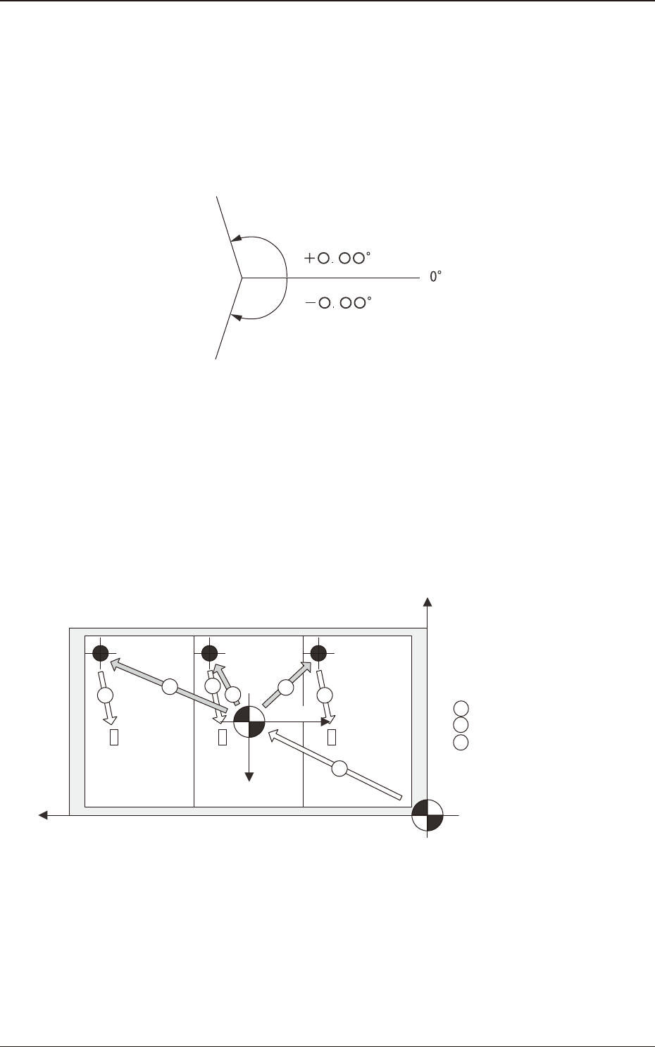
Z (Angle) [deg]
Set the offset value for component placement angle.
The set value is added to the "Offset Z (deg)" of all components in the
placement data (P data).
To correct the angle of component placement counterclockwise, a parameter
must be entered with a plus (+) sign. A minus (-) sign must be afxed for
clockwise correction.
F2B7
X-Direction and Y-Direction
"Same" or "Opposite" can be selected as the X and Y directions in the
placement reference coordinate system.
Same
: Select this when the direction of the coordinates is the same
as that of the machine coordinates.
Opposite
: Select this when the direction of the coordinates is opposite,
compared with the direction of the machine coordinates.
Y+
X+
X+
Y+
1
2
3
2
2
3
3
1 : PCB Origin Offset
2 : Unit PCB Origin
3 : Placement Coordinates
Machine Origin
PCB Origin
Machine Coordinate System
Placement
Coordinate
Reference
Machine Coordinate System
F2B8
Z-Direction
Select one of the following options to determine the Z angular orientation of
the placement coordinate reference point.
Same
: Select this when the angular orientation is the same as that
of the machine coordinates.
Opposite
: Select this when the angular orientation is opposite,
compared with the direction of the machine coordinates.
3.2 PCB
2OM-1751
2-171303-001
(B01_03)
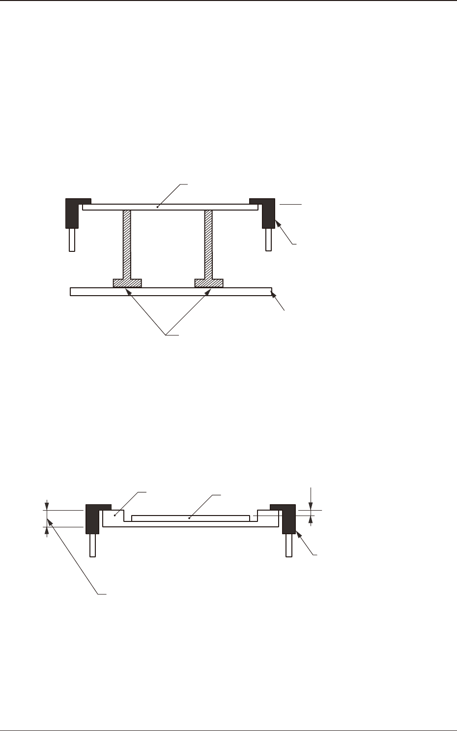
PCB height offset [mm]
Set an offset value as a nozzle descending distance based on the upper
surface of the PCB in the component placement section. This offset value
applies to all components in the pattern program.
Normal Cases
Set "+0.000" (zero) in the text box.
The gure below shows that the upper surface of a PCB is maintained by
the PCB support pins at the PCB upper surface reference.
PCB
PCB Upper Surface
Reference
Chute
Backup Pin
Backup Table
F2B9
Example of Jig PCB Usage
The gure below shows that the upper surface of a PCB is lower than the
PCB upper surface reference.
If "PCB Upper Surface Reference + a" is set as an offset value at this time,
components can be placed correctly on the PCB.
a
T (Thickness)
Jig PCB
PCB
PCB Upper Surface
Reference
Chute
F2B10
3.2 PCB
2OM-1751
2-181303-001
(B01_04)
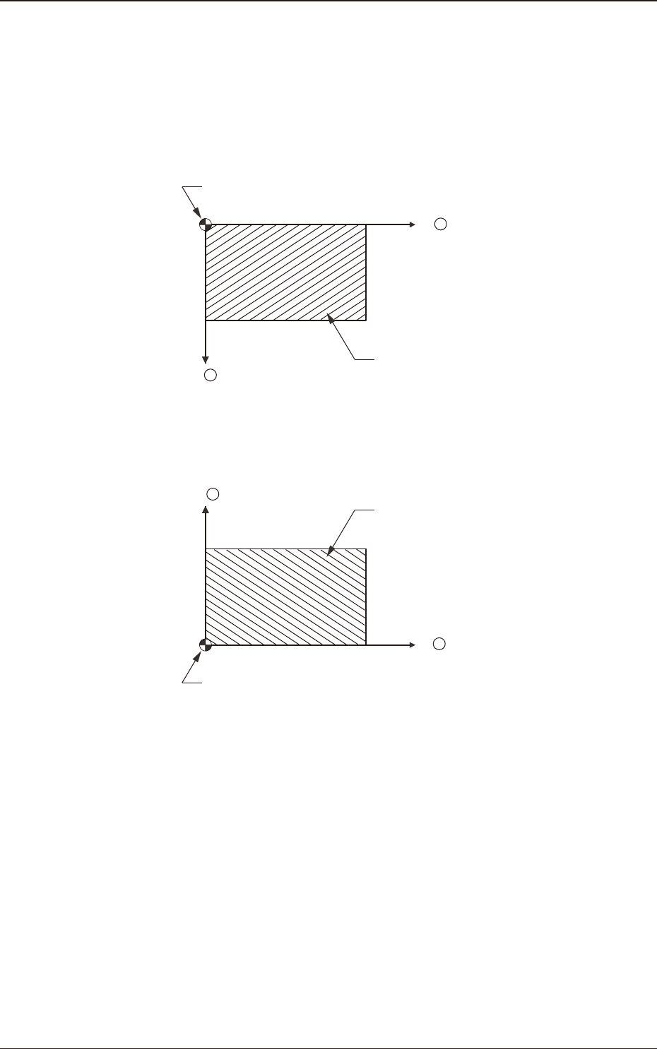
PCB Positioning Reference
Set the PCB positioning reference in this text box. The reference must be
specied according to the input and output machines.
Rear Left
: The placement coordinate reference is based on the rear left
side and specied as follows.
X +
Y +
Placement Coordinate Reference (No)
PCB
F2B11
Front Left
: The placement coordinate reference is based on the front left
side and specied as follows.
X +
Y +
Placement Coordinate Reference (No)
PCB
F2B12
3.2 PCB