2OM-1751-003w_G5S.pdf - 第175页
2OM-1751 2-53 1303-001 (F01_08) Component Library Comment Shown are the comments that were entered in the component library data. (F01_09) Carrier T ype, Dir [deg], and Width [mm] Shown are the values specied in the com…
2OM-1751
2-521303-001
(F01_03)
C
Set control commands in the text boxes.
Notice
If a control command other than the following ones is used, the step
becomes invalid.
- (hyphen)
: This command handles the steps as those for the placement
feeder location data.
E
: This command shows the end of the placement feeder location
data. The step where "E" is set is valid.
S
: This command invalidates the steps specied as placement
feeder location data.
X
: This command invalidates the steps specied as placement
feeder location data and shows the end of the data.
(F01_04)
Comment
Set a comment for each Fdr No.Up to 32 characters (alphanumerics and
symbols) can be used. Alphanumeric characters and symbols can be used.
Note
(a) The performance of the machine is not affected by these commands.
In other words, it has nothing to do with or without these comments.
(b) It is recommended to set helpful information on components related
to the feeder Nos. (Fdr No.).
(F01_05)
Feeder Fixed
Select "Enable" or "Disable" to determine whether or not the feeder positions
should be xed in place. When "Enable" is selected, the feeder Nos.
(Fdr No.) and the component ID are not affected by any insert and delete
operations of a component.
Disable
: The feeder position is not xed.
Enable
: The feeder position is xed.
(F01_06)
Feeder Alternate
Select "Enable" or "Disable" to determine whether or not the feeder alternate
function should be used.
Disable
: The feeder alternate function is not used.
Enable
: The feeder alternate function is used.
(F01_07)
Fdr No.
When "Enable" is selected for the feeder alternate function, set the
destination feeder No. (Fdr No.) of the feeder that will work in place of the
feeder where a component pickup error has occurred in succession.
3.6 CMPNT PL

2OM-1751
2-531303-001
(F01_08)
Component Library Comment
Shown are the comments that were entered in the component library data.
(F01_09)
Carrier Type, Dir [deg], and Width [mm]
Shown are the values specied in the component library data.
(F01_10)
Fd. Pitch [mm]
Shown are the feed pitches specied in the component library data.
(F01_11)
Used Parts
Shown is the number of components to be used for one unit PCB.
(F01_12)
Nozzle Type
Shown is the number of components to be used for one unit PCB.
3.6 CMPNT PL
2OM-1751
2-54
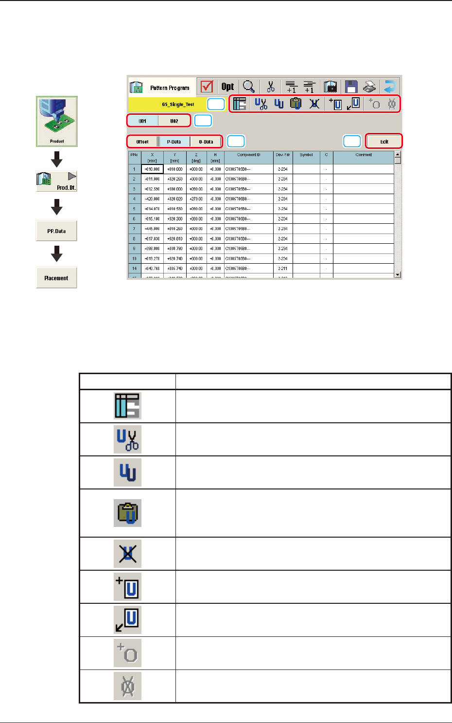
3.7 Placement
(G01) Placement Data
[1]
[2]
[3]
[4]
F2B43
[1] Tool Bar
The operation commands that can be executed in the "Placement" window,
are collectively displayed as icons.
Icons Description
When pressed, the "Symbol Data" window appears.
When pressed, the selected unit is copied and deleted.
The currently displayed U-data is cut out.
When pressed, the selected unit is copied.
The currently displayed U-data is copied.
When pressed, the copied unit is inserted.
The U-data (the selected unit is copied and deleted, or the
selected unit is copied) is pasted.
When pressed, the selected unit is deleted.
The currently displayed U-data is deleted.
When pressed, new unit is added at the end.
New U-data is added to the end of the U-data.
New unit is inserted before the selected unit.
New U-data is inserted before the currently selected U-data.
The O-data is added to the selected unit.
The O-data is added to the currently selected U-data.
The O-data in the selected unit is deleted.
The O-data in the currently selected U-data is deleted.
T2B15
1303-001
3.7 Placement
Graphic
Development