2OM-1751-003w_G5S.pdf - 第183页
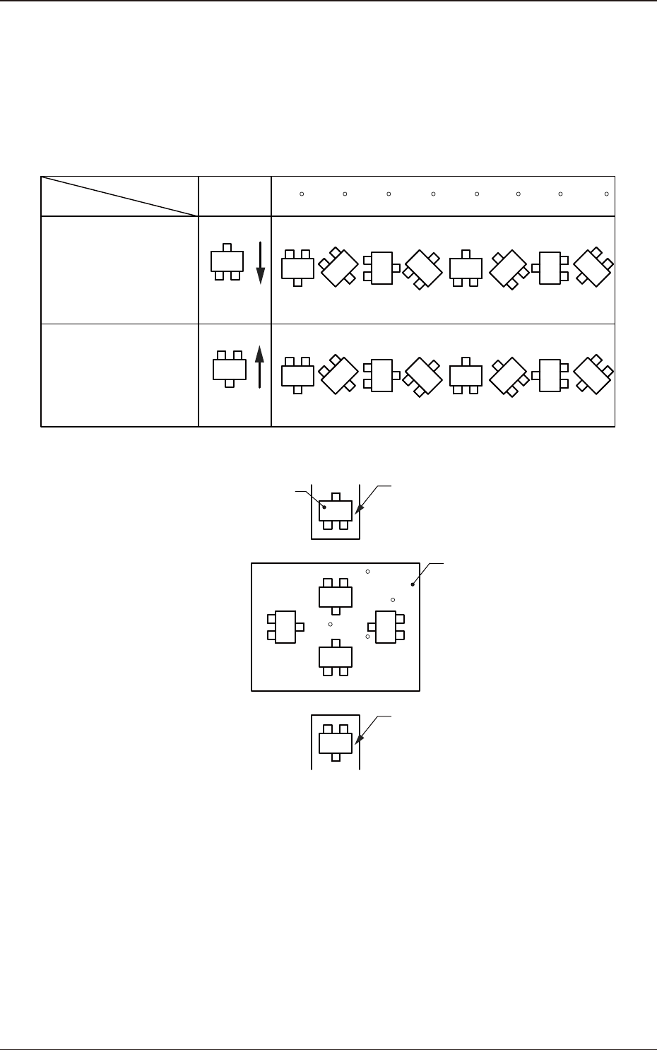
2OM-1751 2-61 (G03_03) Z=theta [deg] Set angles for component placement. The placement angles must be determined according to the packaged posture of components on the tape feeder. Example: 0 45 90 135 180 225 270 315 Fr…

2OM-1751
2-60
(G03) P-Data
When the [P-Data] button is pressed in the "Placement" window, the
following tab sheet appears.
F2B49
(G03_01)
PNo
Shown are the step Nos. of the placement data (P).
Set coordinates and angles for component placement in the lines of the step
Nos. (P-Nos.).
(G03_02)
X [mm] and Y [mm]
Set Coordinates X and Y for component placement. The coordinates must be
based on the placement coordinate reference (N0).
Y2
Y1
X1
X2
Y
X
Placement Coordinate Reference (No)
F2B50
1303-001
3.7 Placement
Graphic
Development
2OM-1751
2-61
(G03_03)
Z=theta [deg]
Set angles for component placement.
The placement angles must be determined according to the packaged posture
of components on the tape feeder.
Example:
0 45 90 135 180 225 270 315
Front Side of Machine
Z=Theta
(Angle)
Feeder Bases #1
Packaged
Posture
User Direction
of Tape Feed
Packaged
Posture
User Direction
of Tape Feed
Feeder Bases #2
Rear Side of Machine
Packaged Posture of
Component on Feeder
Tape Feeder
PCB
Tape Feeder
0
90
180
270
F2B51
1303-001
3.7 Placement
2OM-1751
2-62
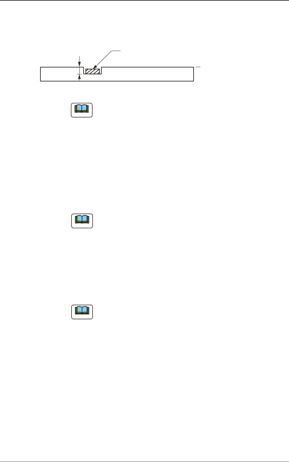
(G03_04)
H [mm]
The component placement height can be corrected.
H
Component
PCB
Reference Plane
F2B52
Note
When a parameter is set as "H" data in the last line (last step No.), it
becomes invalid because "E" is set in the "C (Control Command)" text
box.
(G03_05)
Component ID
Set component IDs in the text boxes.
(G03_06)
Fdr No.
Set the Nos. of the feeders loaded with components.
Note
The feeder Nos. (Fdr Nos.) to be set here must be specied in the
placement feeder location data.
(G03_07)
Symbol
Use them to enter the characters written on the board, for wiring pattern, etc.
Max. 32 characters can be used to set.
Available characters are half-width alphabetical/numerical characters and
symbols.
Note
(a) The automatic operation is not affected by these comments.
(b) The comments can be used to check "Ref. No." printed on the upper
surfaces of PCBs.
1303-001
3.7 Placement