2OM-1751-003w_G5S.pdf - 第186页
2OM-1751 2-64 (G04) O-Data When the [O-Data] button is pressed in the "Placement" window, the following tab sheet appears. F2B53 (G04_01) Ono. Shown are the step Nos. of the placement data (O). These step Nos. …
2OM-1751
2-63
(G03_08)
C
Enter some of the following control commands.
Note
If a control command other than the following ones is used, the step
becomes invalid.
- (hyphen)
: This command handles the steps as those for component
placement.
S
: This command invalidates the steps specied as those for
component placement.
C
: This command invalidates the steps specied as those for
component placement.
Note:
As for dispensers, these steps become valid.
D
: This command handles the steps as those for component
placement.
Note:
As for dispensers, these steps become invalid.
E
: This shows the end of the placement data (O). When
placement data (O) is not created, this shows the end of the
steps in the placement data (P).
P, Q
: This shows the end of the placement data (P) of a repetitive
pattern program.
B : When the unit PCB BBR function (option) is used, set this
control command for P-No. 1. See Note (b).
0, 1, 2, 3, 4, 5, 6, 7, 8, 9:
These control commands are used to enable the block sorting
function. See Note (a).
Note
(a) When the block sorting function is used in the following case, the
productivity will be improved because components are placed on the
specied areas of unit PCBs.
•
It is required to change the nozzles in the nozzle stocker for
component placement on a certain unit PCB according to the
repetitive pattern program.
(b) Do not set the B command in any lines except "P-No. 1".
(c) Conrm that "0" (zero) is set in the "X [mm]", "Y [mm]", "Z=theta
[deg]", "H", and "Fdr No." text boxes of the last line (last step No.)
and set "E", "P", or "Q".
(G03_09)
Comment
Set a comment for each step No. Alphanumeric characters and symbols can
be used. Up to 32 characters (alphanumerics and marks) can be used.
Note
(a) The automatic operation is not affected by these comments.
(b) The comments can be used to check "Ref. No." printed on the upper
surfaces of PCBs.
1303-001
3.7 Placement
2OM-1751
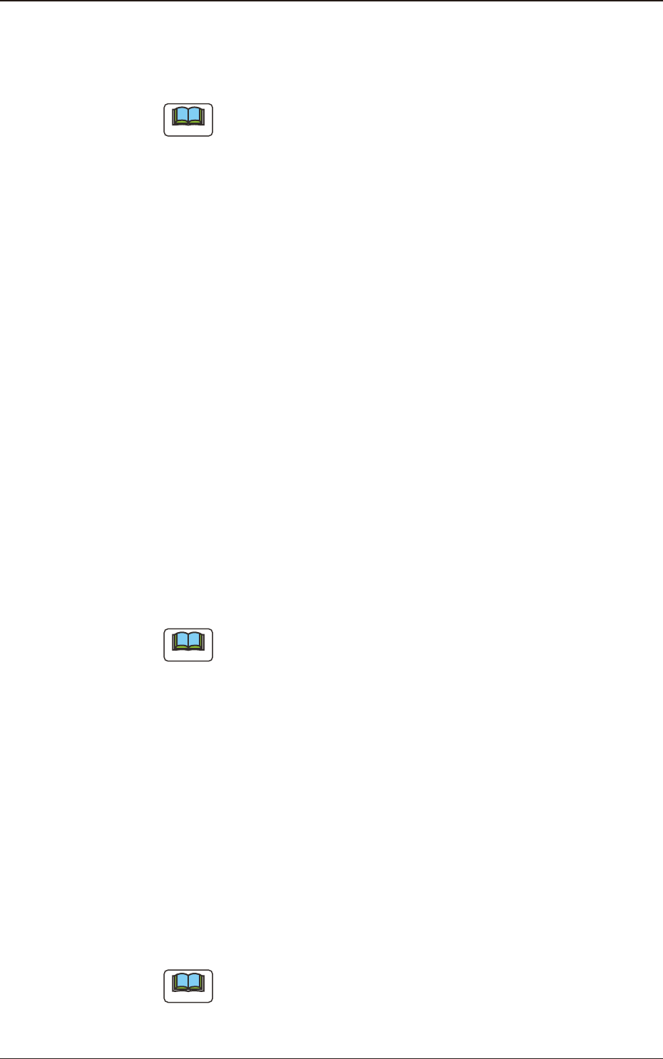
2-64
(G04) O-Data
When the [O-Data] button is pressed in the "Placement" window, the
following tab sheet appears.
F2B53
(G04_01)
Ono.
Shown are the step Nos. of the placement data (O).
These step Nos. are regarded as repetitive pattern Nos. Parameters must be
entered in each line (pattern).
O-No.1
O-No.2
O-No.3
O-No.4
Pattern 4
Pattern 2 Pattern 1
Pattern 3
Example of Repetitive Pattern Program F2B54
1303-001
3.7 Placement
Graphic
Development
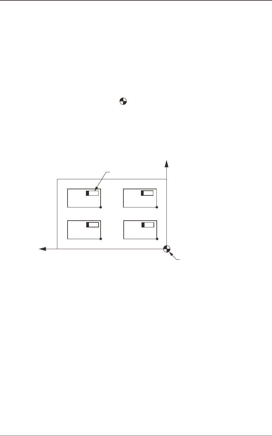
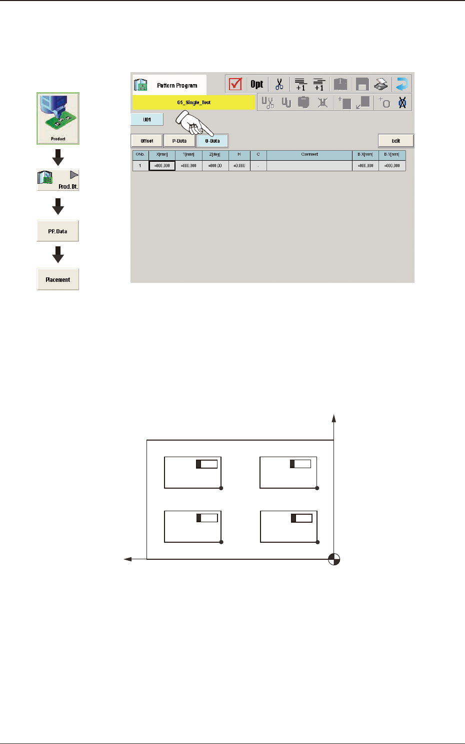
2OM-1751
2-65
(G04_02)
X [mm] and Y [mm]
Set the coordinates of each pattern origin (O01 through On) based on the
placement coordinate reference (N0). A pattern origin refers to the reference
coordinates of a repetitive pattern.
The pattern origins (coordinate reference of repetitive patterns) must
be determined, regarding the "Z=theta [deg]" data as "0°" (described
in "G04_03") and located at corners on the same side as the placement
coordinate reference (N0).
N
0
:
The center of
is the placement coordinate reference.
O
01
:
Pattern Origin of Pattern 1
O
02
:
Pattern Origin of Pattern 2
O
03
:
Pattern Origin of Pattern 3
O
04
:
Pattern Origin of Pattern 4
O04
O03
O02
O01
X
Y
Placement Coordinate
Reference (No)
Component
Pattern 4 Pattern 3
Pattern 2 Pattern 1
Example of Repetitive Patterns F2B55
1303-001
3.7 Placement