2OM-1751-003w_G5S.pdf - 第223页
2OM-1751 4-9 1303-001 B:comp. missing (% of T otal err) Shown are the number of component missing errors detected in the recognition process and the percentage of component missing errors per total number of pickup error…
2OM-1751
4-81303-001
[12]
Test mode time
Shown is the period of time during which test run was performed according
to the test mode parameters.
Note
"Warm-up run time" is included.
[13] Warm-up run time
The running time is counted when the machine is operated under the
following condition.
•
"TEST PATTERN" is enabled in the "Test Mode" window.
•
The "PCB Transfer Dsbl." check box is checked.
(State in which no PCB is put in and out)
[14]
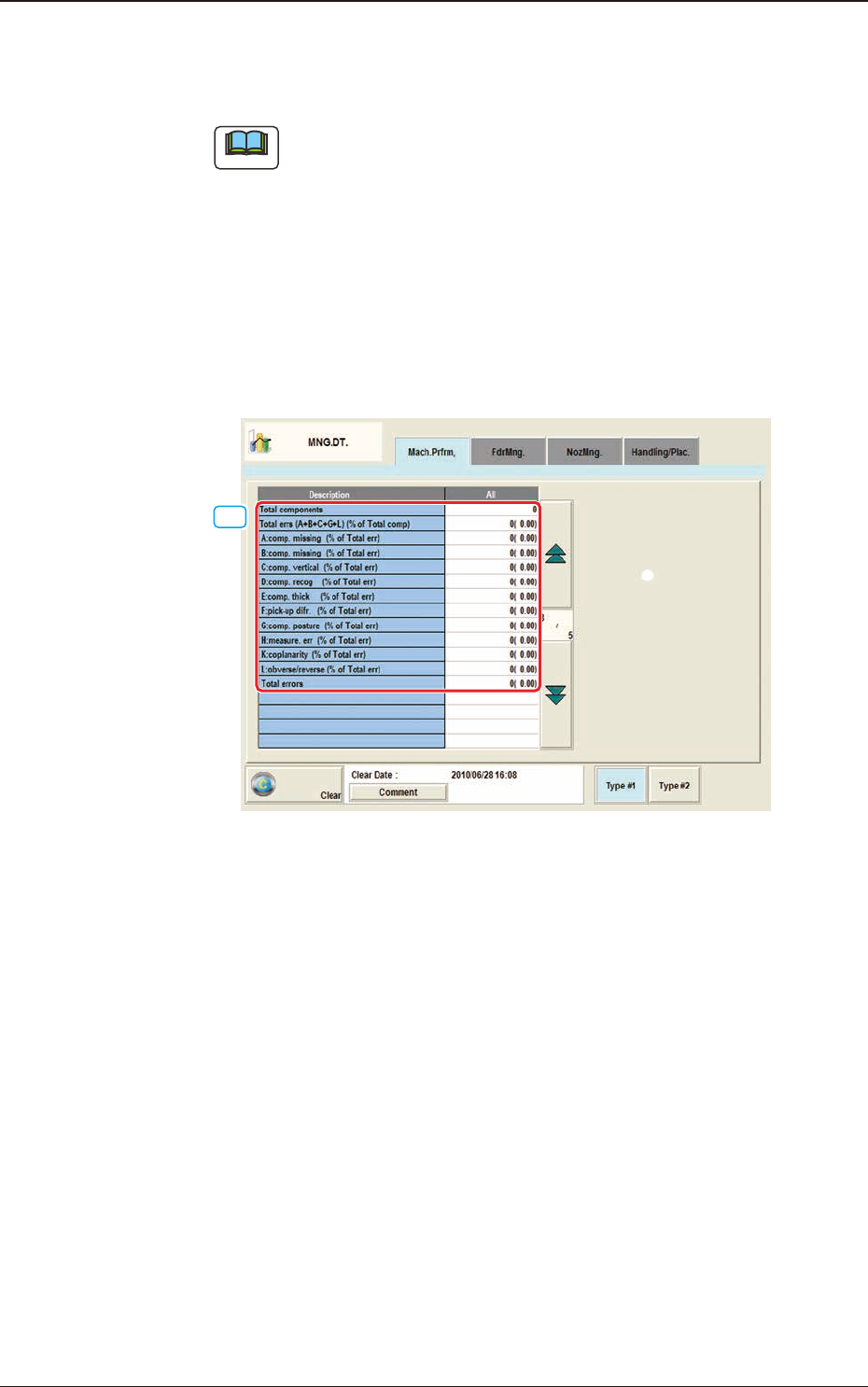
"Mach.Prfrm," Tab Sheet (3/5) F2D5
[14] Tatal componets
No. of the pick-up operation times is displayed in this data box.
Total errs (A+B+C+G+L)/Total cmp ([%])
Shown are the total number of pickup errors, the total number of components
to be picked up, and the percentage of picked components per total number
of pickup errors.
A:comp.missing (% of Total err)
Shown are the number of component missing errors detected by the linear
measure detection sensor and the percentage of component missing errors
per total number of pickup errors.
2.1 "Mach.Prfrm," Tab Sheet

2OM-1751
4-91303-001
B:comp. missing (% of Total err)
Shown are the number of component missing errors detected in the
recognition process and the percentage of component missing errors per total
number of pickup errors.
C:comp. vertical (% of Total err)
Shown are the number of vertical component errors detected by the linear
measure detection sensor and the percentage of vertical component errors per
total number of pickup errors.
D:comp. recog (% of Total err)
Shown are the number of errors detected in the recognition process and the
percentage of errors per total number of pickup errors.
E:comp. thick (% of Total err)
Shown is the percentage of component thickness errors detected by the linear
measure detection sensor per total number of pickup errors.
F:pick-up difr. (% of Total err)
Shown are the number of pickup difference errors detected in the recognition
process and the percentage of the errors per total number of pickup errors.
G:comp. posture (% of Total err)
Shown are the number of reversed component and polarity judgment errors
detected in the recognition process and the percentage of the errors per total
number of pickup errors.
H:measur. err (% of Total err)
The measurement value error count and percentage to the total error count
are displayed in this data box.
K:coplanarity (% of Total err)
The percentage of error detected in the optional device installation, is
displayed in this data box.
L:obverse / reverse (% of Total err)
The percentage of the error times in the front/rear judgment using the linear
measure to the pick-up error total times, is displayed in this data box.
Total errors
Shown is the total number of component handling errors.
2.1 "Mach.Prfrm," Tab Sheet
2OM-1751
4-10
[15]
"Mach.Prfrm," Tab Sheet (4/5) F2D6
[15]
[16]
[17]
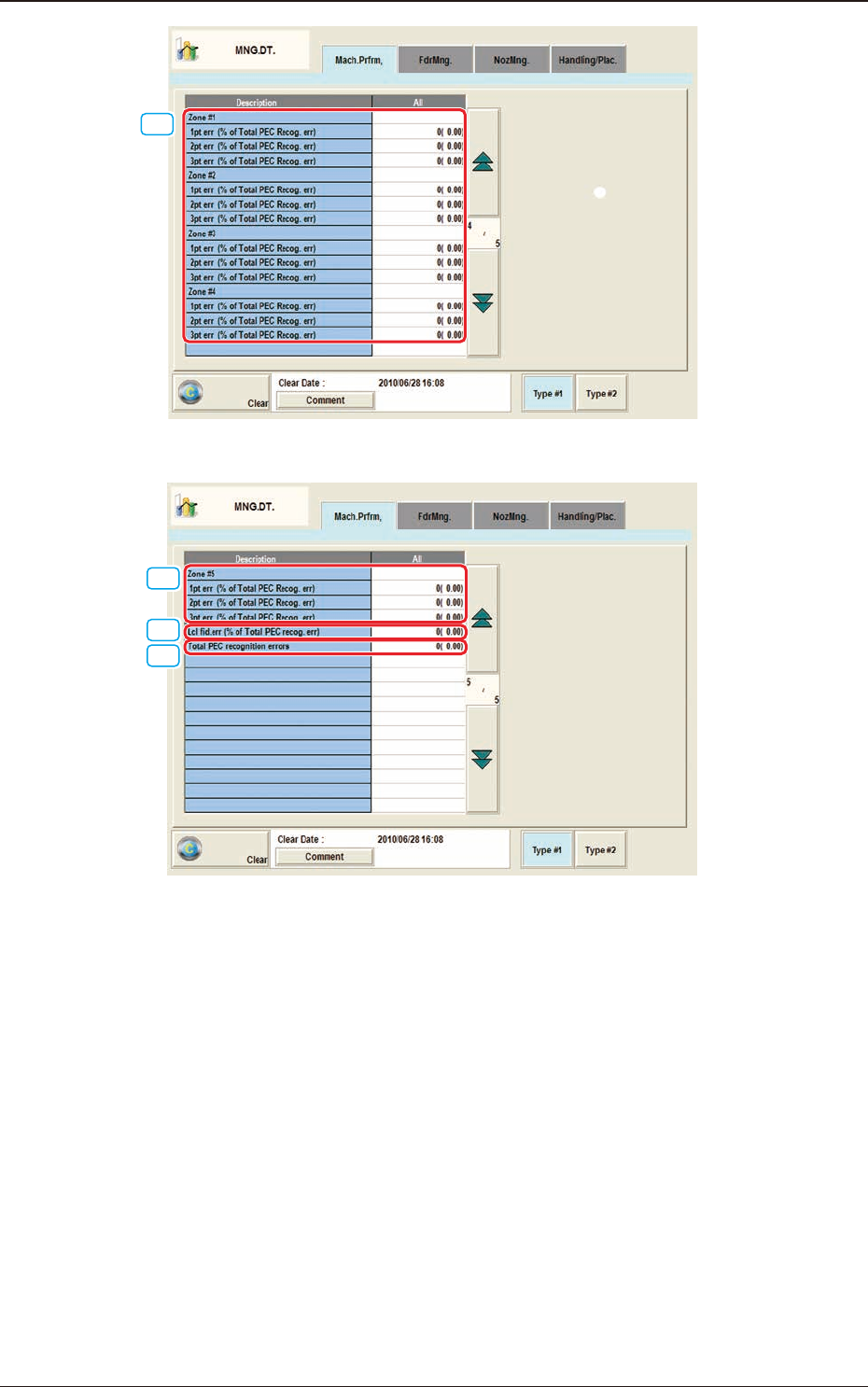
"Mach.Prfrm," Tab Sheet (5/5) F2D7
[15] Zone #1 through #5
1pt err (% of Total PEC Recog. err)
Shown are the total number of errors detected on the rst ducial mark and
the percentage of the detected errors per total number of all errors detected
by the PEC recognition function.
2pt err (% of Total PEC Recog. err)
Shown are the total number of errors detected on the second ducial mark
and the percentage of the detected errors per total number of all errors
detected by the PEC recognition function.
1303-001
2.1 "Mach.Prfrm," Tab Sheet