2OM-1751-003w_G5S.pdf - 第283页
2OM-1751 6-1 1 1303-001 (5) Close the transparent cover and press the cover lock switch. (6) Press the [Product Opn T arget Pos Movement] button. In 10 seconds, press the [ST AR T] button on the operation panel. (The con…
2OM-1751
6-101303-001
4.1 Collection of PCB Support Pins and Setup Operation of
Conveyor Width
•
For Support Pin Manual Change)
The PCB support pins are used to keep the upper surface of the PCB in proper
height for stabilization of the component placement. If the conveyor width is
not correctly set, the PCB support pins cannot be attached correctly.
Note
When 0402 and 0603 components must be placed, it is important to secure the
atness of the PCB. Use the support pins or a backup plate.
Consult the marketing department or sales agency of Yamaha Motor Co., Ltd.
for how to make a backup plate.
CAUTION
The load power to the motors, etc., is turned OFF
but the setup operation must be performed carefully
when you put your hand inside the machine. Avoid
hand and nger injuries.
Procedure
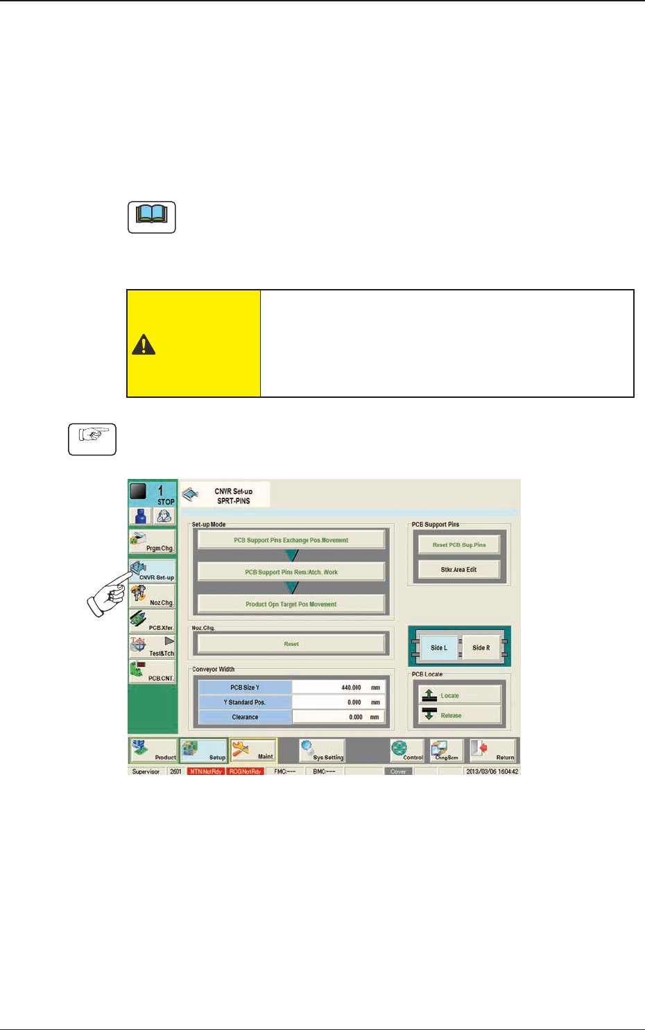
(1) Press the [Setup] button on the submenu bar to display the "SPRT-PINS"
window.
F2F10
(2) Press the [PCB Support Pins Exchange Pos. Movement] button.
After that, press the [START] button on the operation panel in 10 sec.
(The machine retracts the head and maximizes the conveyor width.)
(3) Press the cover lock switch.
(The transparent cover will be unlocked).
(4) Open the transparent cover and remove the support pins.
4.1 Collection of PCB Support Pins and Setup Operation of Conveyor Width
2OM-1751
6-111303-001
(5) Close the transparent cover and press the cover lock switch.
(6) Press the [Product Opn Target Pos Movement] button.
In 10 seconds, press the [START] button on the operation panel.
(The conveyor width is changed appropriate for the selected pattern
program.)
(7) Press the pertinent cover lock switch. The lamp of the switch extinguishes.
(The transparent cover (door type) is unlocked. )
(8) Open the transparent cover (door type).
(9) Insert the PCB support pins vertically to the holes on the backup table.
(Be sure to set up the PCB support pins such that they are dispersed to
support the object PCB equally.)
Notice
Do not put your hand or any heavy object on the backup table while
working with the backup table. Otherwise, the backup table may become
deformed due to an excessive load.
(10) Conrm that a PCB support pin, etc., is not left behind on the backup table.
(Conrm that no component or dust, etc., has fallen into the holes on the
backup table.)
(11) Close the transparent cover (door type).
(12) Press the cover lock switch. The lamp of the switch illuminates.
(The transparent cover (door type) is locked.)
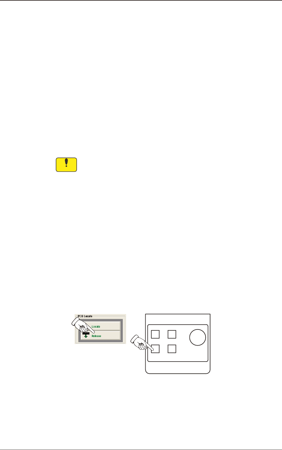
(13) Press the [Release] button in the "PCB Locate" group box.
In 10 seconds, press the [START] button on the operation panel.
(The backup table moves down.)
POWER ON
STOP
PNL CHANGE
START
F2F11
4.1 Collection of PCB Support Pins and Setup Operation of Conveyor Width

2OM-1751
6-121303-001
•
For Support Pin Automatic Change
Procedure
(1) Press the [Setup] button on the submenu bar to display the "SPRT-PINS"
window.
F2F12
(2) Press the [PCB Support Pins Exchange Pos. Movement] button.
After that, press the [START] button on the operation panel in 10 sec.
(The machine retracts the head and maximizes the conveyor width.)
(3) Press the [PCB Support Pins Rem./Atch. Work] button and within 10
seconds, press the [START] button on the operation panel.
(The support pin attachment or removal will be performed automatically).
Note
When the support pins are to be changed automatically, prepare the nozzle
(PK01) in the nozzle stocker.)
(4) Press the [Product Opn Target pos Movement] button and within 10 seconds,
press the [START] button on the operation panel.
(The conveyor width will be changed according to the selected pattern
program).
4.1 Collection of PCB Support Pins and Setup Operation of Conveyor Width