2OM-1751-003w_G5S.pdf - 第289页
2OM-1751 6-17 1303-001 (6) Make sure that no PCB support pins are left on the backup table. (Make sure that no components or debris drop into any of the backup table holes). (7) Close the transparent covers. (8) Press th…
2OM-1751
6-16
4.2.1 Stocker Area Edit Procedure
Note
This section is described based on the front reference and PCB ow direction
from left to right.
Procedure
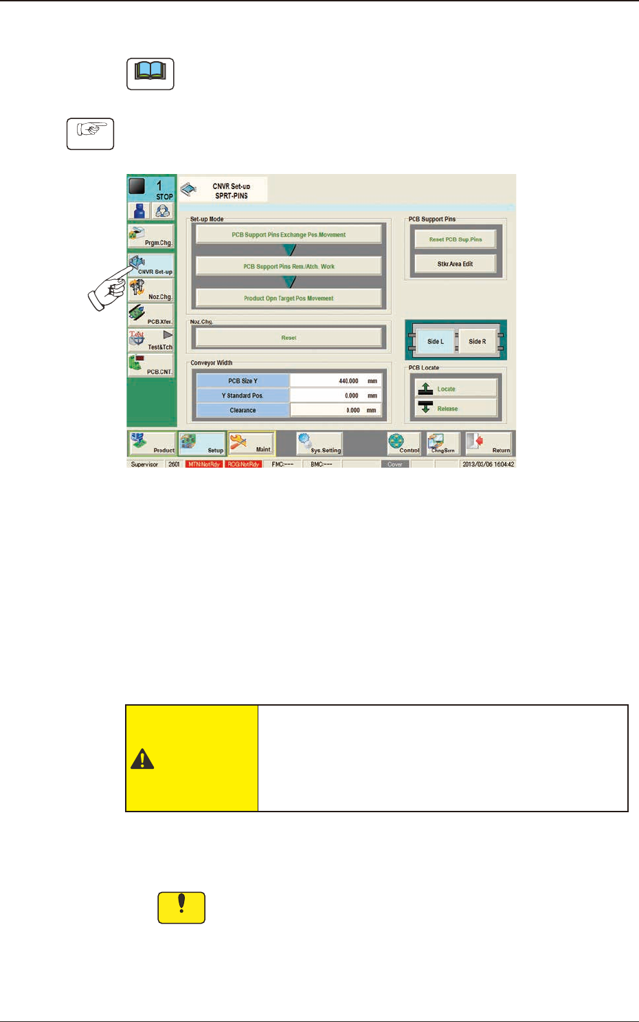
(1) Press [Sprt-Pins] button in the "Setup" main menu bar to display the
following window.
F2F16
(2) Press the [PCB Support Pins Exchange Pos. Movement] button and within
10 seconds, press the [START] button on the operation panel.
(The head will retract and the conveyor width becomes the maximum one.)
(3) Press the cover lock switch and turn off the light on the switch.
(The transparent covers are unlocked).
(4) Open the transparent covers.
CAUTION
The load power to the motors, etc., is turned OFF
but the setup operation must be performed carefully
when you put your hand inside the machine. Avoid
hand and nger injuries.
(5) Insert the PCB support pins directly into each hole in the stock area on the
backup table.
Notice
In the case that any operation is to be performed on the backup
table, when any strong pressure is applied to the backup table such
as touching the backup table with your hand to support your body
or putting an object on the backup table, it might be deformed. Take
the greatest care.
1303-001
4.2 "Stkr.Area Edit" Window
2OM-1751
6-171303-001
(6) Make sure that no PCB support pins are left on the backup table.
(Make sure that no components or debris drop into any of the backup table
holes).
(7) Close the transparent covers.
(8) Press the cover lock switch to turn ON the light on the switch.
(The transparent covers are locked).
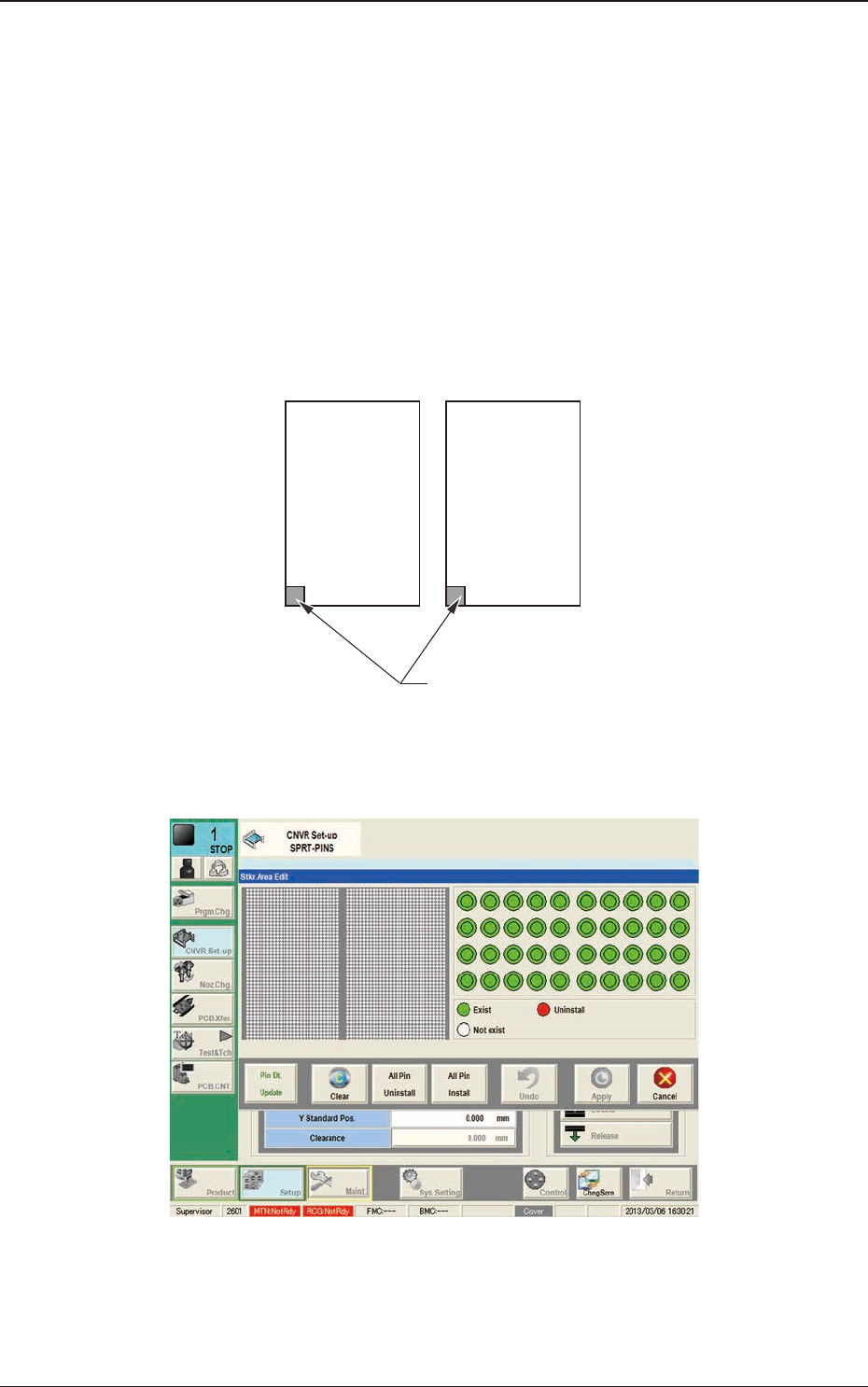
(9) Using the PCB locating section selection button, select the stock area for
which the parameters are edited.
Side L Side R
Stkr.Area
F2F17
(10) Press the [Stkr Area Edit] button to display the following window.
F2F18
4.2 "Stkr.Area Edit" Window
2OM-1751
6-181303-001
(11) Edit the parameters in the stock area image display section so that the setup
condition is the same as that for the support pins in the stock area.
Note
When the setup operation is stopped due to an error, press the [Clear]
button to clear the arrangement data for the PCB support pins on the
backup stage.
(12) Press the [Apply] button.
(The "Conrm" window will be displayed).
(13) Press the [OK] button.
(The editing operation will be ended).
F2F19
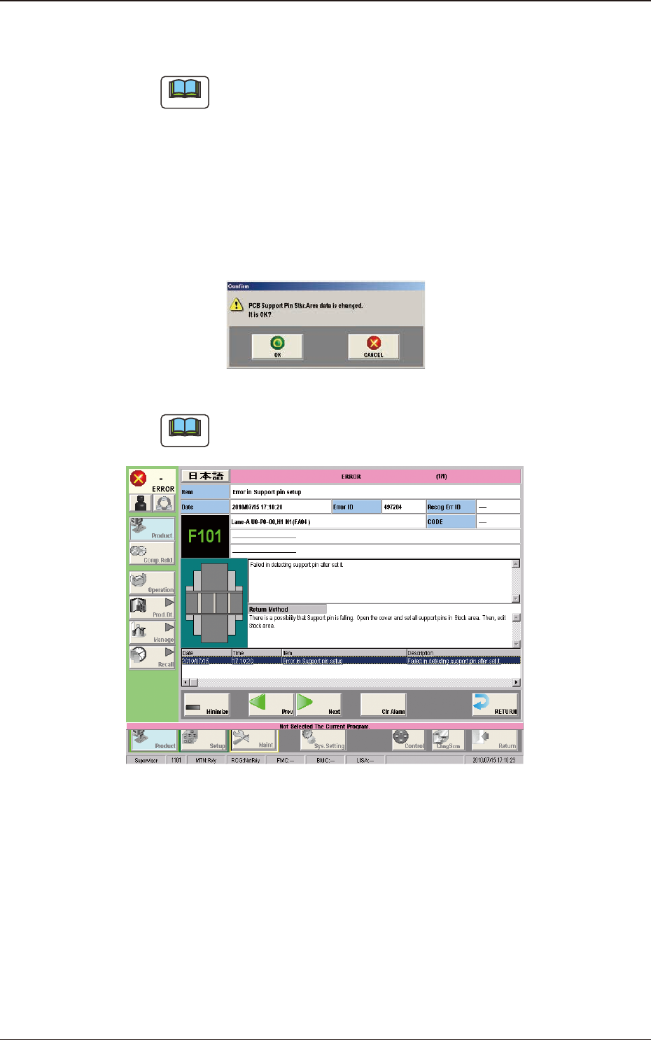
Note
When any error occurs, the PCB support pins should be re-setup.
Perform the procedure from Step (3).
F2F20
4.2 "Stkr.Area Edit" Window