2OM-1751-003w_G5S.pdf - 第290页
2OM-1751 6-18 1303-001 (1 1) Edit the parameters in the stock area image display section so that the setup condition is the same as that for the support pins in the stock area. Note When the setup operation is stopped du…
2OM-1751
6-171303-001
(6) Make sure that no PCB support pins are left on the backup table.
(Make sure that no components or debris drop into any of the backup table
holes).
(7) Close the transparent covers.
(8) Press the cover lock switch to turn ON the light on the switch.
(The transparent covers are locked).
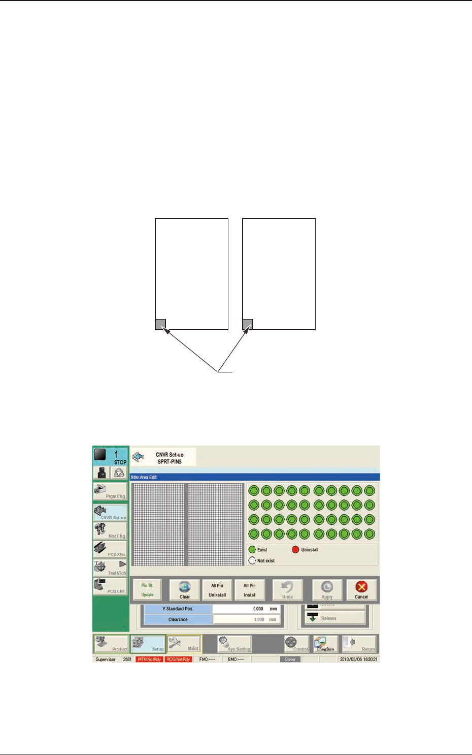
(9) Using the PCB locating section selection button, select the stock area for
which the parameters are edited.
Side L Side R
Stkr.Area
F2F17
(10) Press the [Stkr Area Edit] button to display the following window.
F2F18
4.2 "Stkr.Area Edit" Window
2OM-1751
6-181303-001
(11) Edit the parameters in the stock area image display section so that the setup
condition is the same as that for the support pins in the stock area.
Note
When the setup operation is stopped due to an error, press the [Clear]
button to clear the arrangement data for the PCB support pins on the
backup stage.
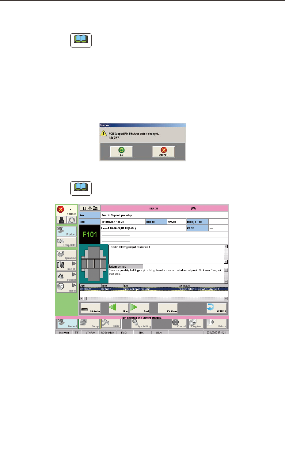
(12) Press the [Apply] button.
(The "Conrm" window will be displayed).
(13) Press the [OK] button.
(The editing operation will be ended).
F2F19
Note
When any error occurs, the PCB support pins should be re-setup.
Perform the procedure from Step (3).
F2F20
4.2 "Stkr.Area Edit" Window
2OM-1751
6-191303-001
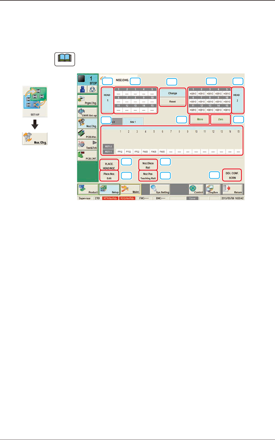
5. "NOZ.CHG." Window
For the nozzle change, the "Overall Setup" or "Manual Setup" operation is
performed.
Note
The window shows the condition where a multi-functional head is mounted onto
the head No. 1 position.
[1]
[2]
[4]
[5]
[6]
[7]
[8]
[9]
[10]
[11]
[3] [3][2]
F2F21
[1] "Nozzle Stocker Status Indicator" Panel
Indicated is the status of the nozzle stockers.
The background color of the "Bypassed"-specied address turns yellow.
[2] "Vacuum Nozzle Status Indicator" Field
Indicated is the status of the nozzles attached to each head.
[3] Head Selection Buttons
Press the [#1], the [#2], the [#3] or the [#4] buttons to select the head for
which some nozzles should be changed.
The background color of the selected button turns pea green.
[4] Nozzle Operation Buttons
The following buttons are provided.
When the [START] button on the operation panel is pressed in 10 seconds
after the button corresponding to the required operation is selected and the
[Move] button is pressed, the machine performs the selected operation for
the nozzle.
Graphic
Development
5. "NOZ.CHG." Window