2OM-1751-003w_G5S.pdf - 第313页
2OM-1751 6-41 7.2.3 Placement Position T each Operation Procedure Note The following describes the procedure based on the assumption that "Front Right" is selected as placcment coordinate references. "Pn&q…

2OM-1751
6-40
[3] Graphic Image Move Buttons (
Buttons)
When the arrow direction is touched in the recognition image display area,
the image is moved in the corresponding direction.
[4] [OK] Button
When pressed, the matching position is conrmed.
[Cancel] Button
When pressed, this button cancels the manual alignment operation.
[5] [Back] Button
When pressed, the "Place Pos Teach" window is returned.
1303-001
7.2 "Place Pos Teach" Window
2OM-1751
6-41
7.2.3 Placement Position Teach Operation Procedure
Note
The following describes the procedure based on the assumption that "Front
Right" is selected as placcment coordinate references.
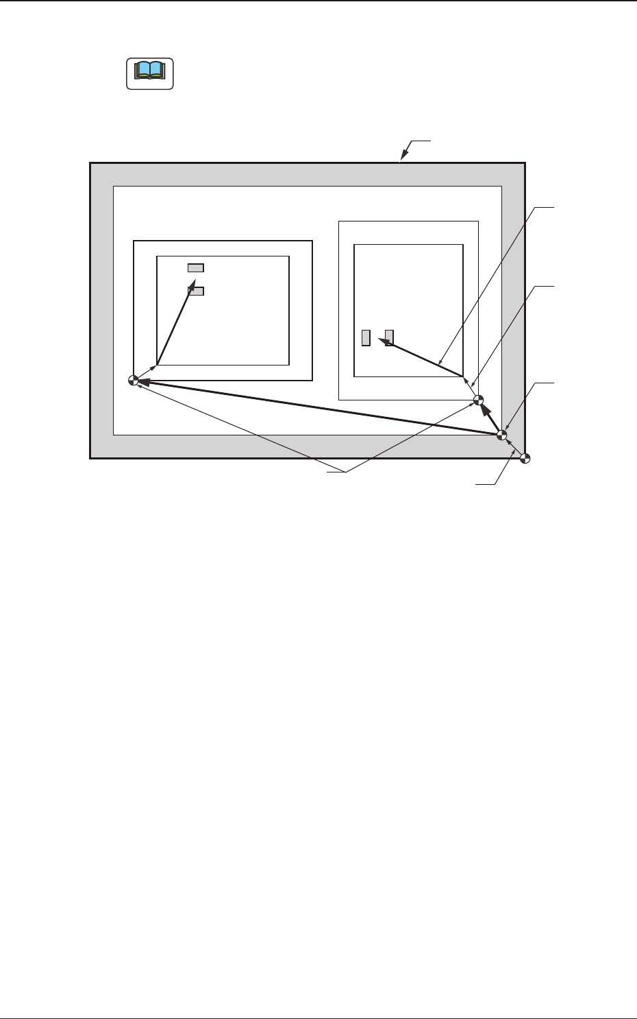
"Pn" and "On" are taught as follows.
Unit Pattern Angle : 270°
Unit Pattern Angle : 0°
Pn
Pn
PCB Outermost Shape
Placement
Position
O
2
O1
Placement Position
Reference
Pattern Origin
Unit Control
Offset
PCB Origin
PCB Origin Offset
F2F40
1303-001
7.2 "Place Pos Teach" Window
2OM-1751
6-42
Automatic Teaching
•
Data to be Taught
The following are data items to be taught.
•
PCB Placement Position P1 to Pn Step (X, Y) on Placement Data (P).
•
Pattern Origin O1 to On Coordinates (X, Y) on the placement Data (O).
•
Notes on Teaching Operation
When the PEC recognition is set to ON on the pattern program data, all the
PEC recognition processing should be completed before the placement position
check in the placement position teach operation.
If the PEC recognition has been set to ON, when the teaching is started while
the machine is stopped, the PEC recognition will be performed at rst.
Procedure
(1) Select the pattern program (production model) to be taught and prepare for
PCBs, etc.
(2) Select the "Cycle run" in the "Place Pos Teach" window and set the
movement speed.
(3) To nd the overall shifting tendency of the PCB patterns, press the [START]
button on the operation panel in 10 seconds after the [Cycle run] button.
(4) Select the component outline and the condition of the pattern displayed while
the X/Y beam is working and select the step to be taught.
Note
When the patterns of a certain step are specically shifted to one side, it is
required to teach the P-data. When the overall patterns of a unit PCB are
uniformly shifted to one side, the O-data must be taught.
(5) Press the [Back] button.
(Return to the "Place Pos Teach" window.)
Reference
Refer to "F2 "Place Pos Teach" window", "F3 "Recognition" window for
Placement Position Teaching" or "F4 "Recognition" window in Manual
Alignment Mode" for the button positions.
1303-001
7.2 "Place Pos Teach" Window