2OM-1751-003w_G5S.pdf - 第314页
2OM-1751 6-42 Automatic Teaching • Data to be T aught The following are data items to be taught. • PCB Placement Position P1 to Pn Step (X, Y) on Placement Data (P). • Pattern Origin O1 to On Coordinates (X, Y) on the pl…
2OM-1751
6-41
7.2.3 Placement Position Teach Operation Procedure
Note
The following describes the procedure based on the assumption that "Front
Right" is selected as placcment coordinate references.
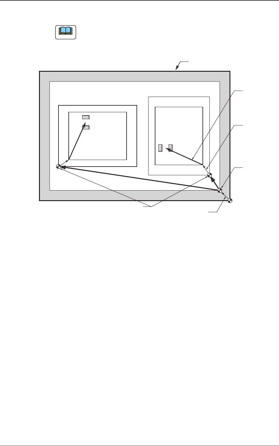
"Pn" and "On" are taught as follows.
Unit Pattern Angle : 270°
Unit Pattern Angle : 0°
Pn
Pn
PCB Outermost Shape
Placement
Position
O
2
O1
Placement Position
Reference
Pattern Origin
Unit Control
Offset
PCB Origin
PCB Origin Offset
F2F40
1303-001
7.2 "Place Pos Teach" Window
2OM-1751
6-42
Automatic Teaching
•
Data to be Taught
The following are data items to be taught.
•
PCB Placement Position P1 to Pn Step (X, Y) on Placement Data (P).
•
Pattern Origin O1 to On Coordinates (X, Y) on the placement Data (O).
•
Notes on Teaching Operation
When the PEC recognition is set to ON on the pattern program data, all the
PEC recognition processing should be completed before the placement position
check in the placement position teach operation.
If the PEC recognition has been set to ON, when the teaching is started while
the machine is stopped, the PEC recognition will be performed at rst.
Procedure
(1) Select the pattern program (production model) to be taught and prepare for
PCBs, etc.
(2) Select the "Cycle run" in the "Place Pos Teach" window and set the
movement speed.
(3) To nd the overall shifting tendency of the PCB patterns, press the [START]
button on the operation panel in 10 seconds after the [Cycle run] button.
(4) Select the component outline and the condition of the pattern displayed while
the X/Y beam is working and select the step to be taught.
Note
When the patterns of a certain step are specically shifted to one side, it is
required to teach the P-data. When the overall patterns of a unit PCB are
uniformly shifted to one side, the O-data must be taught.
(5) Press the [Back] button.
(Return to the "Place Pos Teach" window.)
Reference
Refer to "F2 "Place Pos Teach" window", "F3 "Recognition" window for
Placement Position Teaching" or "F4 "Recognition" window in Manual
Alignment Mode" for the button positions.
1303-001
7.2 "Place Pos Teach" Window

2OM-1751
6-43
Manual (Manual Axis Operation) Teaching
Procedure
(1) Specify the teaching mode with the buttons in the "Teach Mode" group box.
For the teaching method, select "AUTO" or "Center".
(2) Select [Cycle run] button or [Select Step] button, move the X/Y beam to the
object step.
(After pressing each buttons, operate as follows.)
•
Press the [START] button on the operation panel in 10 seconds after the
[Cycle run] button to start the automatic movement.
After the X/Y beam has moved to the object step for the teaching
operation, stop the beam with the [STOP] button on the operation panel.
•
Press the [START] button on the operation panel in 10 seconds after the
[Select Step] button. Repeat this until the X/Y beam moves to the object
step for the teaching operation.
•
Use the vertical scroll bar in the "Step Data" pane or select the object step
for the teaching operation with the [Dsig Step] button.
(3) Press the START button on the operation panel in 10 seconds after the
[TEACH] button.
(4) Using the graphic image move buttons, match the component outer
shape shown in the recognition area with the PCB pattern captured in the
recognition memory image, and when the position is decided, press the [OK]
button to determine the position.
(5) When the teaching operation is completed, new placement position is
displayed in the position teaching's "Teac Res" text boxes (X, Y) in the
"Place Pos Teach" window. Check them.
(New placement position is registered temporarily and written in the le.)
Note
(a) The Temp Entry function of the new placement position saves the
temporary le for the data for operation and pattern program le, but
does not overwrite the data on the original le.
(b) The temporarily entered step data can be cancelled. When it is to
be cancelled, select the step to be cancelled and press the [Cncl Dt]
button.
(c) The temporarily entered step data is indicated with a blue background.
(d) The temporarily entered data is immediately reected on the Auto
Move and Step Move operations.
(e) While the new placement position is being registered temporarily, it
becomes impossible to edit the current pattern program data.
(f) When all data items are to be cancelled, refer to (6).
1303-001
7.2 "Place Pos Teach" Window