2OM-1751-003w_G5S.pdf - 第371页
2OM-1751 6-99 1303-001 7.4.2 PEC Recognition T est Procedure • PEC Recognition T est Preparation Procedure (1) Open the "PP CHANGE" window from the "Setup" main menu to set the pattern program. (2) T …
2OM-1751
6-981303-001
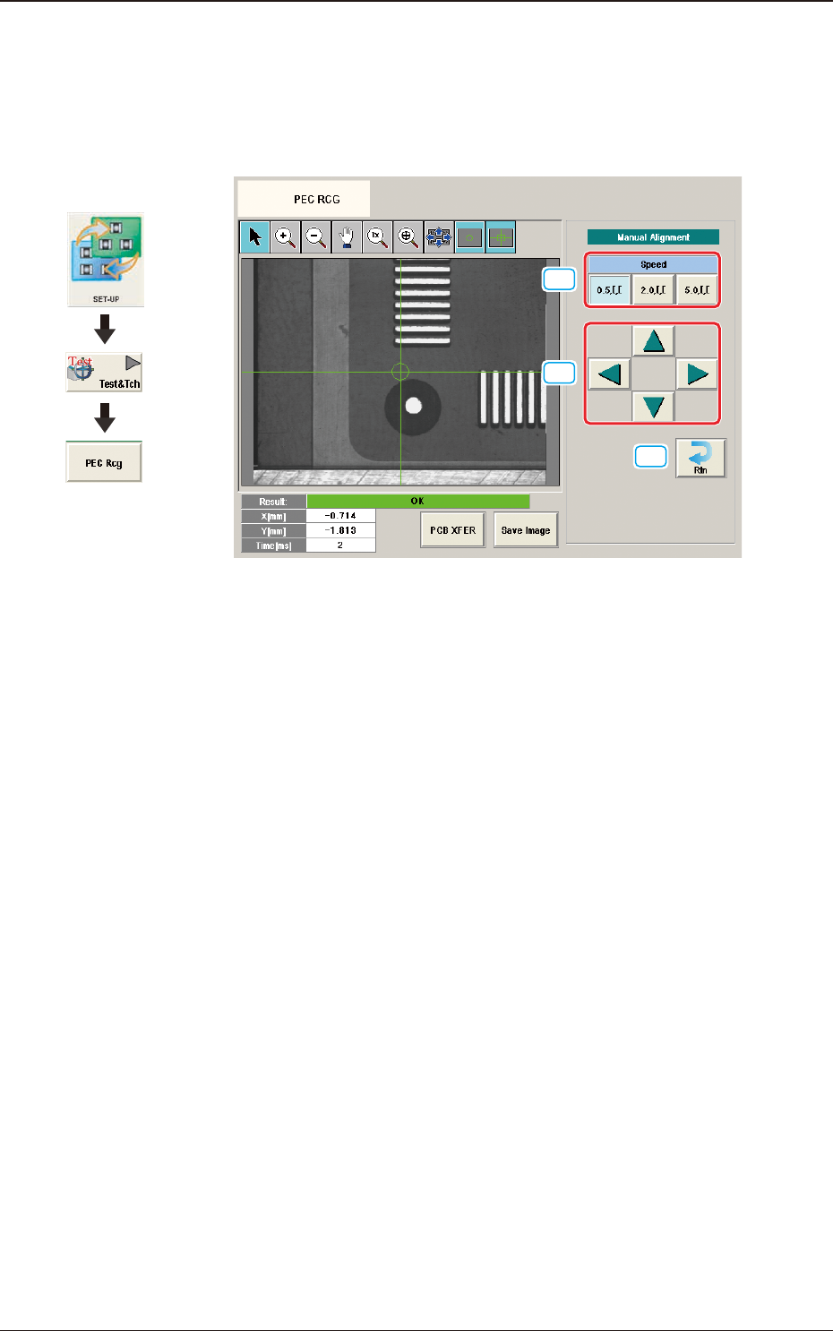
7.4.1 Manual Alignment Operation
The PEC recognition position is located using the manual alignment operation.
When the [Manual Alignment] button is pressed after the [Move] button is pressed
on the "PEC RCG" test window, the "Manual Alignment" window appears.
[1]
[2]
[3]
F2F117
[1] [Speed] Button
The beam movement speed in the manual alignment operation is selected
from the following items.
[0.5 mm] Button, [2.0 mm] Button, [5.0 mm] Button
[2] Manual Alignment Operation
When pressed, the beam is moved at the speed selected in "[1] Speed Setup"
in the arrow direction.
[3] [Rtn] Button
When pressed, the "PCB Test" window is returned.
7.4 "PEC RCG" Test Window
Graphic
Development
2OM-1751
6-991303-001
7.4.2 PEC Recognition Test Procedure
•
PEC Recognition Test Preparation
Procedure
(1) Open the "PP CHANGE" window from the "Setup" main menu to set the
pattern program.
(2) Transfer the PCB to be tested onto the PCB positioning section on the "PCB
XFER" window selected from [Product.] menu or "PCB XFER" window
displayed by pressing the [PCB XFER] button in the "PEC RCG" test
window.
(3) Display the "Move to Setup Position" window or "Setting from Recog Data"
window and set each parameter for PEC recognition position and PEC
recognition mark.
Note
Selecting [Zone n] and [#n] for the global recognition position in the [Set
Data (Crnt.PP.)] window, can set the position data and PEC recognition
mark code.
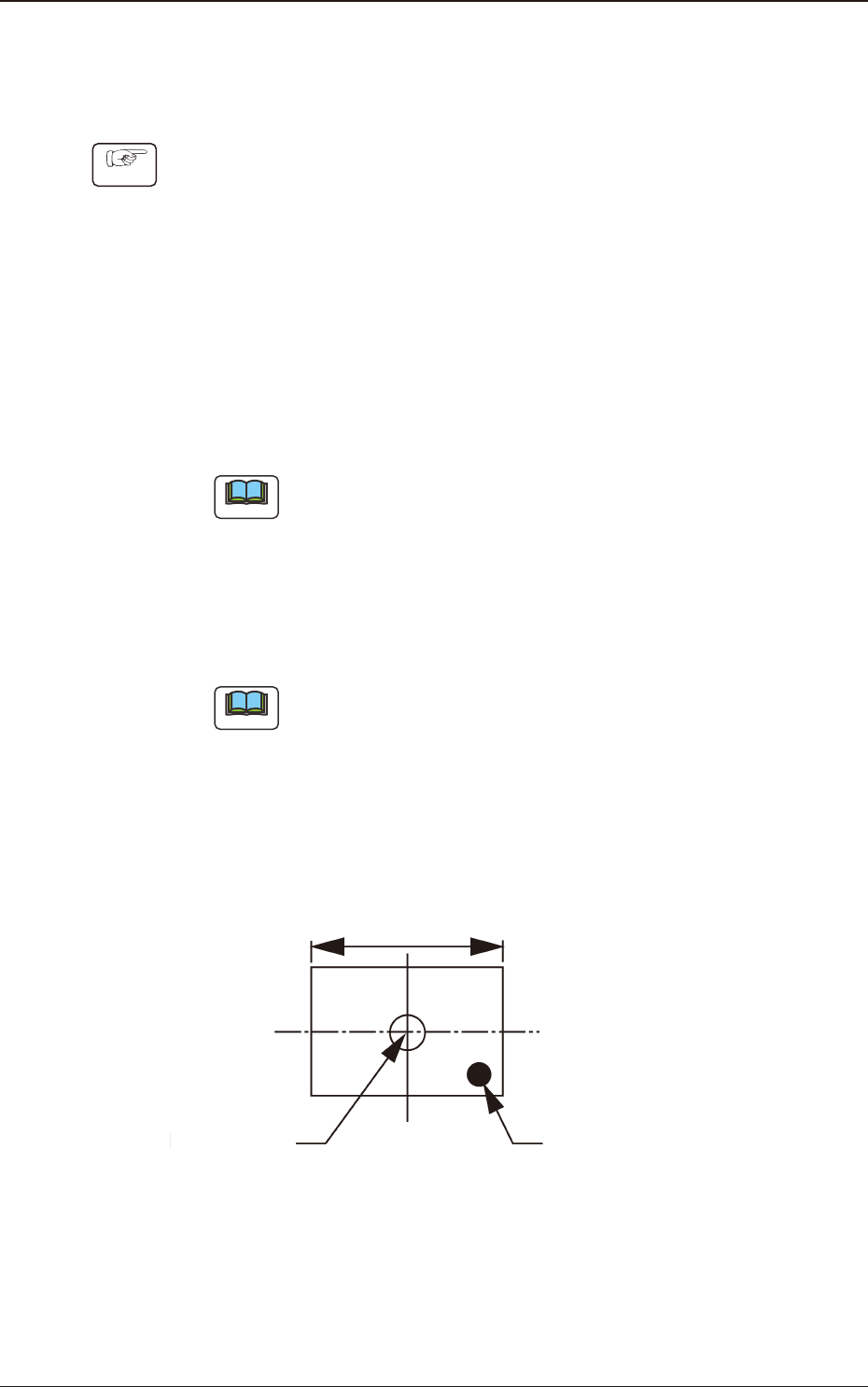
(4) Set the XY beam movement position so that the PEC recognition mark with
which the PEC recognition test is performed, is within the recognition range
(camera view).
Note
For the XY beam movement operation, there are two ways; one is
"Move to Setup Position" where the movement destination is setup using
numerical value and the other is "Manual Alignment Operation" where
the recognition window is displayed and the XY beam position is adjusted
using the manual alignment operation, viewing the recognition image.
Locate the recognition mark close to a corner of the recognition range as
shown in the following gure.
Center of the
Recognized Image
Recognition Mark
Recognition Range
F2F118
7.4 "PEC RCG" Test Window
2OM-1751
6-1001303-001
•
Move to Setup Position
Procedure
(1) Display the "Set from PP" window and conrm the movement destination.
(2) When the [START] button on the operation panel is pressed within 10
seconds after the [Move] button is pressed, the XY beam is moved to the
specied position.
•
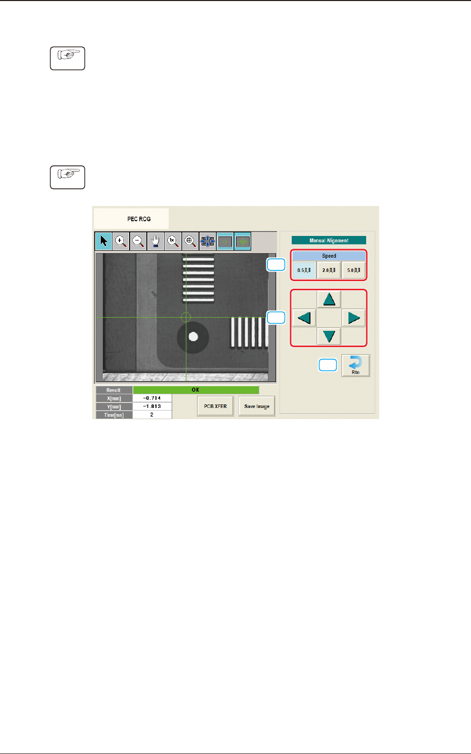
Manual Alignment Operation
Procedure
(1) Display the "Manual Alignment Move" window.
[1]
[2]
[3]
F2F119
(2) Setup the XY beam movement speed using the "Manual Alignment Move"
operation.
(3) Press the direction button (Upper, Right, Lower or Left Arrows) to setup the
beam movement direction.
(4) Press the [START] button on the operation panel within 10 seconds after
pressing the direction button,
(The XY beam will be moved to the recognition test position).
7.4 "PEC RCG" Test Window