2OM-1751-003w_G5S.pdf - 第373页
2OM-1751 6-101 1303-001 • PEC Recognition T est Execution Procedure (1) Press the [ST AR T] button on the operation panel within 10 seconds after pressing the [Recog] button. (The PEC recognition operation are performed.…
2OM-1751
6-1001303-001
•
Move to Setup Position
Procedure
(1) Display the "Set from PP" window and conrm the movement destination.
(2) When the [START] button on the operation panel is pressed within 10
seconds after the [Move] button is pressed, the XY beam is moved to the
specied position.
•
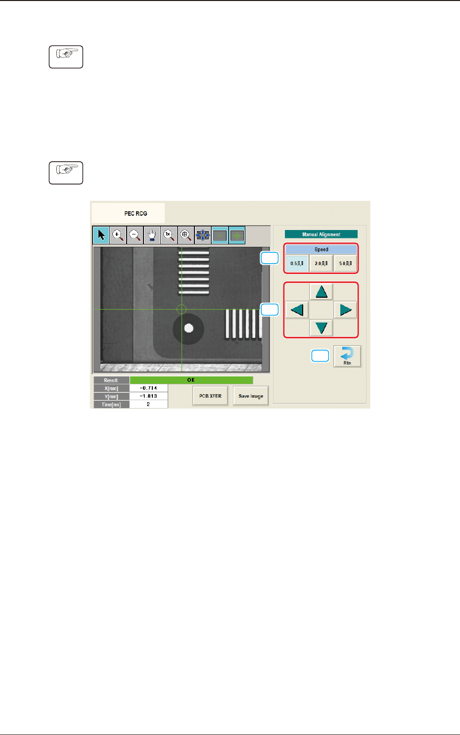
Manual Alignment Operation
Procedure
(1) Display the "Manual Alignment Move" window.
[1]
[2]
[3]
F2F119
(2) Setup the XY beam movement speed using the "Manual Alignment Move"
operation.
(3) Press the direction button (Upper, Right, Lower or Left Arrows) to setup the
beam movement direction.
(4) Press the [START] button on the operation panel within 10 seconds after
pressing the direction button,
(The XY beam will be moved to the recognition test position).
7.4 "PEC RCG" Test Window

2OM-1751
6-1011303-001
•
PEC Recognition Test Execution
Procedure
(1) Press the [START] button on the operation panel within 10 seconds after
pressing the [Recog] button.
(The PEC recognition operation are performed.)
When the "Mrk Pos Align" has been set to "Enable" and the recognition test
is completed successfully, the XY beam is moved so that the PEC recognition
mark is located at the center on the recognition monitor.
•
When the recognition test fails, an error (recognition error) window
appears.
Collect each parameter referring to the descriptions in the "Error" window
and perform the PEC recognition test again.
•
When the recognition test is completed successfully, make a note of
collected parameters and reect them onto the pattern program data for the
product PCB to be tested.
7.4 "PEC RCG" Test Window
2OM-1751
6-1021303-001
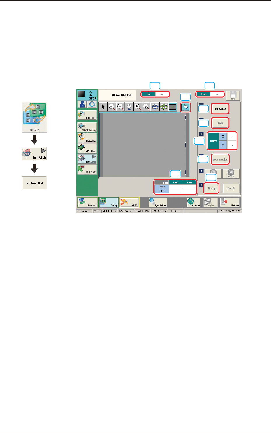
7.5 "PU Pos Ofst Tch" Window
For the components which can not be picked up at its center, the teaching for the
pick-up position is performed.
The manual alignment operation is performed from the current eccentric pick-up
position, of which data obtained by means of adding the data of component center
position correction, simple package shape and pick-up angle.
[1] [2]
[9]
[3]
[4]
[5]
[6]
[7]
[8]
F2F120
[1] Fdr
The Feeder No. to be used to pick-up the component is displayed in this data
box.
[2] Head
The head No. to be used to perform the teaching operation is displayed in
this data box.
[3] Pick-up Position Offset
The pick-up position correction values on the component library data are
displayed for the components in the specied feeder No.
Before
: Value before the teaching operation
After
: Resultant value after the teaching operation
[4] [Fdr Select] Button
When this button is pressed, the "Fdr Select Form" window is displayed.
In this window, the feeder to be used to perform the teaching operation, is
selected.
Graphic
Development
7.5 "PU Pos Ofst Tch" Window