2OM-1751-003w_G5S.pdf - 第376页
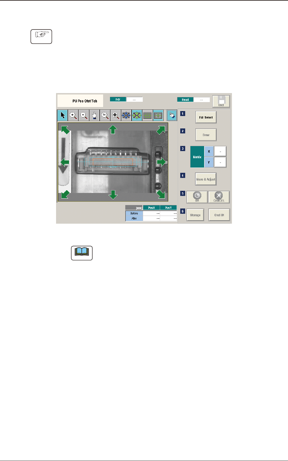
2OM-1751 6-104 • T eaching Procedure Procedure (1) Press the [Fdr Select] button to select the feeder for which the teaching operation is performed. (2) Press the [Move Adjust] button. (The recognition window will be dis…

2OM-1751
6-1031303-001
[5] [Draw] Button
This button is used for the multi-layer tray feeder (option).
[6] Matrix
This group box is used for the multi-layer tray feeder (option).
[7] [Move & Adjust] Button
This button is used to manual alignment operation for the pick-up position.
[8] [Storage] Button
This button is used for the multi-layer tray feeder (option).
[9] [Re-Recogition] Button
After pressing this button, the recognition image is touched in the matching
window to re-recognize the pockets.
Note
When the pocket recognition is unavailable due to the feeder type, the [Re-
Recognition] button is not displayed.
•
Re-Recognition Procedure
Procedure
(1) Press the [Re-Recognition] button in the Matching Window.
(2) Touch the position around the pocket to be re-recognized.
(The graphic image is moved).
7.5 "PU Pos Ofst Tch" Window
2OM-1751
6-104
•
Teaching Procedure
Procedure
(1) Press the [Fdr Select] button to select the feeder for which the teaching
operation is performed.
(2) Press the [Move Adjust] button.
(The recognition window will be displayed to enable the manual alignment
operation).
F2F121
Note
In the case that the subject for which the manual alignment operation is
not within the camera view, press the button on the recognition window to
return the "Eye Match Guide" window and move the beam.
(3) Move the eccentric pick-up position of the subject for which the manual
alignment operation is performed, so that it is the center of the cross hairs
using the image movement button in the recognition window.
(4) Press the [OK] button to determine the position.
(The teaching results are displayed in the data boxes for the pick-up position
corrected values.)
(5) Press the [Save] button.
(The conrmation window for the data saving will be displayed).
•
When [Yes] is pressed, the data is reected on the component library data
and saved.
•
When [No] is pressed, the data saving operation is stopped.
1303-001
7.5 "PU Pos Ofst Tch" Window
2OM-1751
6-1051303-001
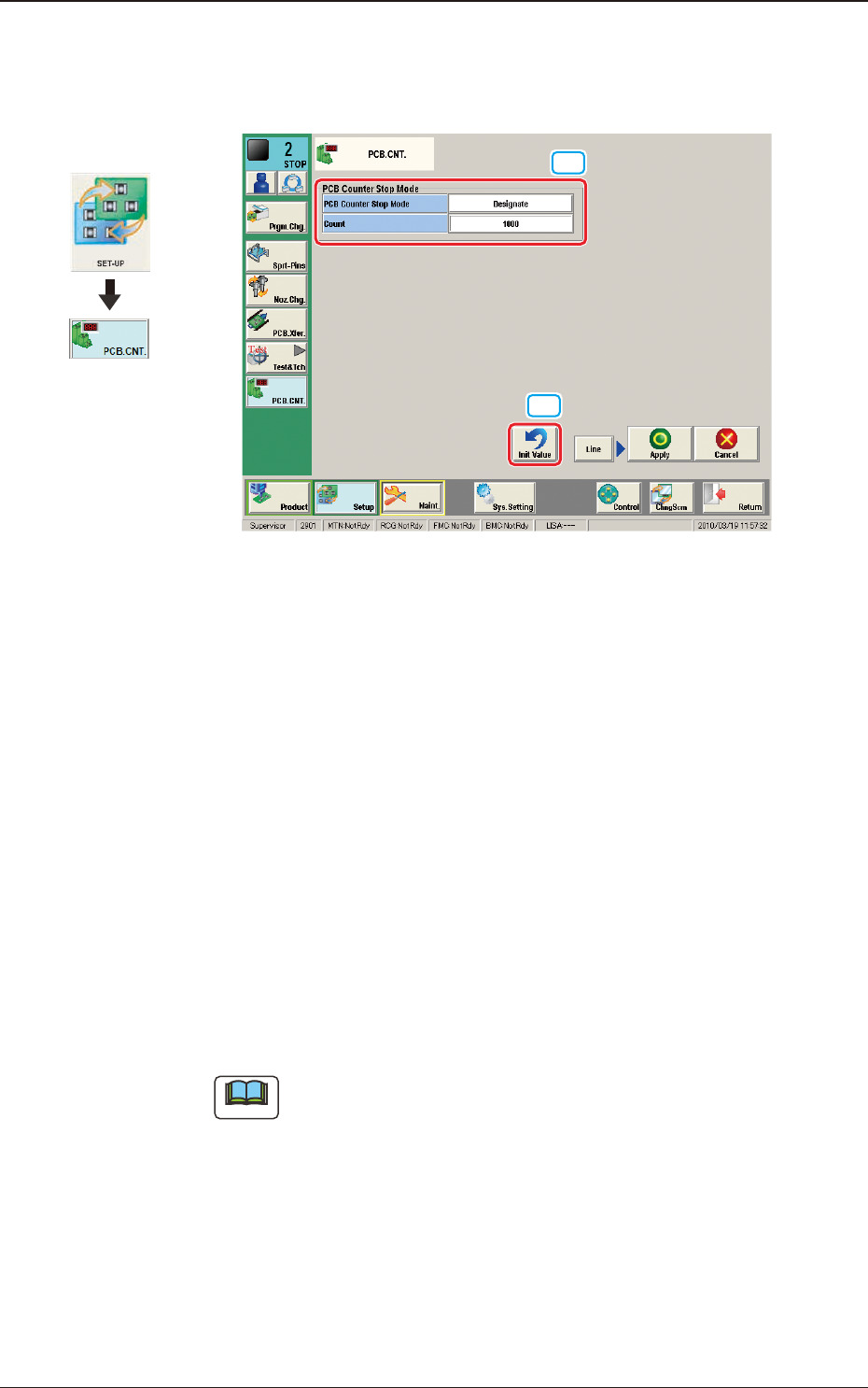
8. "PCB.CNT." Window
This window enables the operator to set the number of PCBs to be produced.
[2]
[1]
F2F122
[1] PCB Counter Stop Mode
PCB Counter Stop Mode
[Designate] Button
: When this button is selected and the
produced PCBs reach the value set in
"Count" text box, the PCB intake is
stopped and after all the PCBs in the
machine are discharged, the machine is
automatically stopped.
[No Designate] Button
: When this button is selected, the PCB
counter stop mode is not used.
Count
The number of produced PCBs for each lane for stopping the machine using
the PCB Counter Stop Mode, is set in this group box.
Note
The set count is displayed in the "Count" data box in the "AUTO. OPN"
window.
[2] [Init Value] Button
When this button is pressed, the set value for the "PCB Counter Stop Mode"
is returned to the initial value.
Graphic
Development
8. "PCB.CNT." Window