2OM-1751-003w_G5S.pdf - 第56页
2OM-1751 1-4 1303-001 [2] Graphic Display Area The graphic image of the PCB transfer and component input sections is displayed in this area. Note The displayed contents will differ depending on selection of the options. …
2OM-1751
1-31303-001
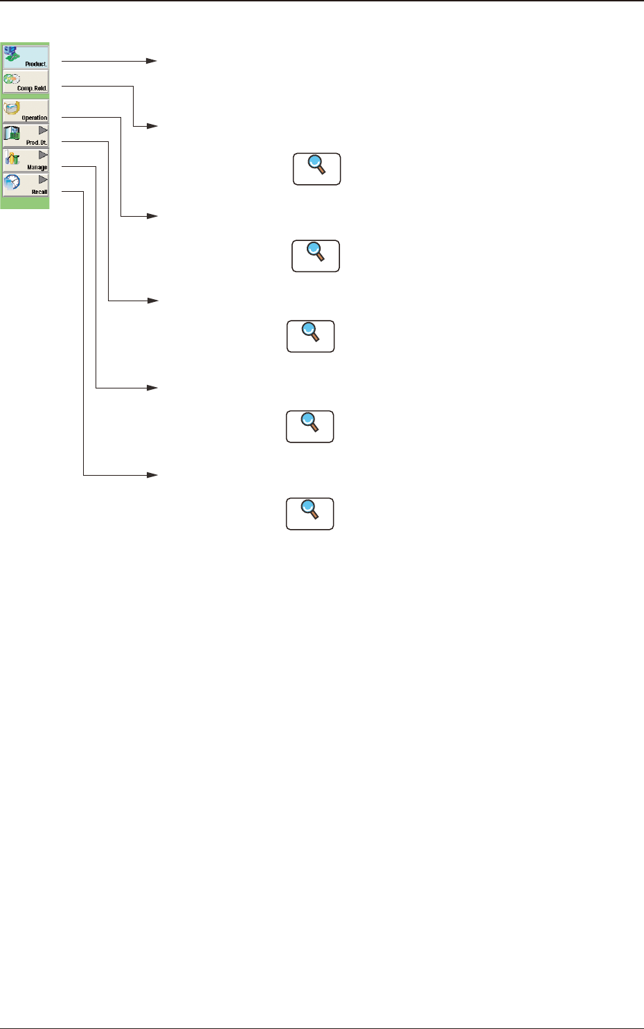
[1] "Product." Main Menu Bar
[Product.]
Main Menu
Opens the "product" window. In normal cases,
this window opens as an initial one.
[Comp.Reld.]
Main Menu
Opens the "Comp.Reload" window.
Refer to "3. "Comp.Reload" Window"
for details .
[Operation]
Main Menu
Opens the "OPERATION" window.
Refer to "4. "OPERATION" Window"
for details.
[Prod.Dt.]
Main Menu
Opens the "Prod.Dt." window.
:
[Manage]
Main Menu
Opens the "Manage" window.
Refer to "Management Data in chapter 4" for
details.
:
[Recall]
Main Menu
:
:
:
:
Reference
Reference
Reference
Opens the "Recall" window.
Refer to "Recall in chapter 5" for details.
Reference
Refer to "Pattern Program in chapter 2" and
"Component Library in chapter 3" for details.
Reference
"Product." Main Menu Bar F2A3
2.1 Local Window
2OM-1751
1-41303-001
[2] Graphic Display Area
The graphic image of the PCB transfer and component input sections is
displayed in this area.
Note
The displayed contents will differ depending on selection of the options.
Feeder status (Pick-up Rate)
(2) 201 to 260
(Feeder Component Data)
PCB Process Status
(2) 101 to 160
Placement Step Count
(3)
(4)
(1)
Graphic Display Area F2A4
(1) Local / Line Change Buttons
Using these buttons, the graphic display section is changed.
Note
When the line consists of a single unit, the line control change
button is not displayed.
[Local] Button
: When this button is pressed, the graphic image of
the single machine is displayed.
[Line] Button
: When this button is pressed, the graphic image of
the line is displayed.
The line start or line stop after the completed PCB
is discharged from the line, is performed.
Reference
Refer to "2.2 Line Window" for the details.
2.1 Local Window
2OM-1751
1-5
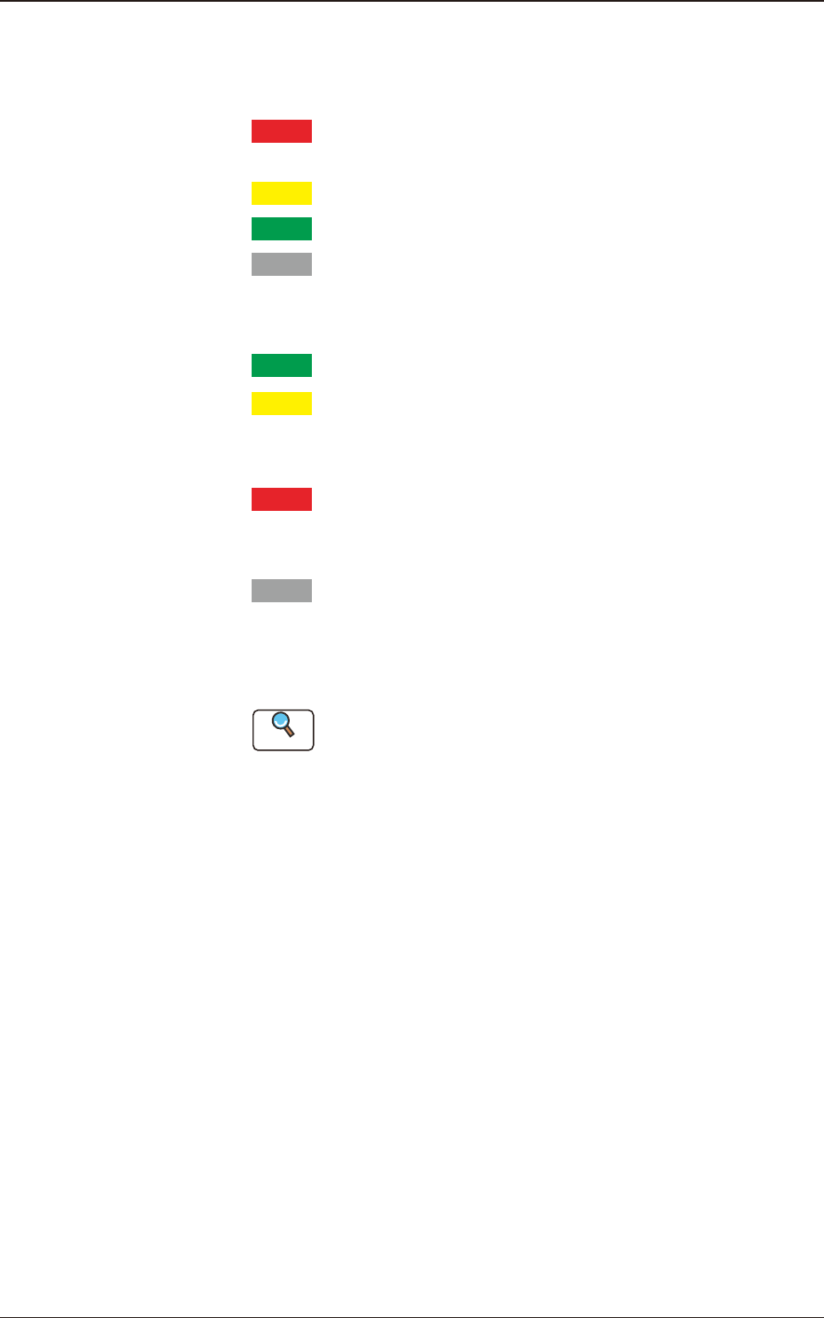
(2) Feeder Status
The current status of the feeder base is classied by color and
displayed. How to understand the status of each color is as follows.
Red
: There are some feeders of which pick-up rate is remarkably
dropped.
Yellow
: There are some feeders of which pick-up rate is dropped.
Green
: The pick-up condition is normal.
Gray
: It shows an unused feeder.
The component reload data for the corresponding feeder is displayed
in this section.
Green
: All feeders are normal.
Yellow
: There are some feeders for which the close attention is
required, such as the feeders with the component shortage
alarm.
Red
: There are some feeders which can not be used because of
component shortage or because the feeder has not been
installed.
Gray
: It shows an unused feeder.
(3) [Cover READY] Buttons
Using this button, the transparent cover lock/unlock status is displayed.
Reference
Refer to "2.3.1 Feeder Ready Switches and 2.3.2 Cover Lock
Switches" in "Chapter 1 (Vol. 1)" for the cover lock switches on the
main body of the machine.
(4) Product PCB Status
The PCB under placement is shown in dark green and the standby
PCB is shown in pale green.
1303-001
2.1 Local Window