2OM-1751-003w_G5S.pdf - 第64页
2OM-1751 1-12 1303-001 3. "Comp.Reload" Window [1] [3] [4] [2] [7] [6] [5] [8] [9] [11] [12] [10] "Comp.Reload" Window F2A11 Note The displayed contents will dif fer depending on selection of the opti…
2OM-1751
1-111303-001
[6] Line Ctrl
[Start] Button (Line Start)
When this button is pressed and the [Start] button on the operation panel
is pressed, the machines (including the printer) in the line, are started up
together.
Note
(a) The start-up operation is available from any machine in the line.
(b) Press the start button after all the machines to be operated have been
set to production READY condition.
When any of the machines has not been set to production READY
condition, the start-up together is not available.
(c) When the machines are started up together, the tower light ashes for
three seconds and the buzzer sounds.
[Product] Button (Line Discharge)
When this button is pressed, the PCB discharge stop is performed in the
machines in the line from the upstream machine.
Note
This operation is available from any machine in the line.
[7] Production Data
The production data for the SIGMA Series line is displayed in this area.
Prod PCB
The product PCB production completion time is displayed in this data box.
Process time
The product PCB production completion time is displayed in this data
box.
(The PCB completion time on the pattern program management data is
displayed in this data box).
Rate of err [%]
The product model pick-up error rate is displayed in this data box.
(The pick-up error rate on the pattern program management data is
displayed).
2.2 Line Window
2OM-1751
1-121303-001
3. "Comp.Reload" Window
[1]
[3]
[4]
[2]
[7]
[6]
[5]
[8]
[9]
[11]
[12]
[10]
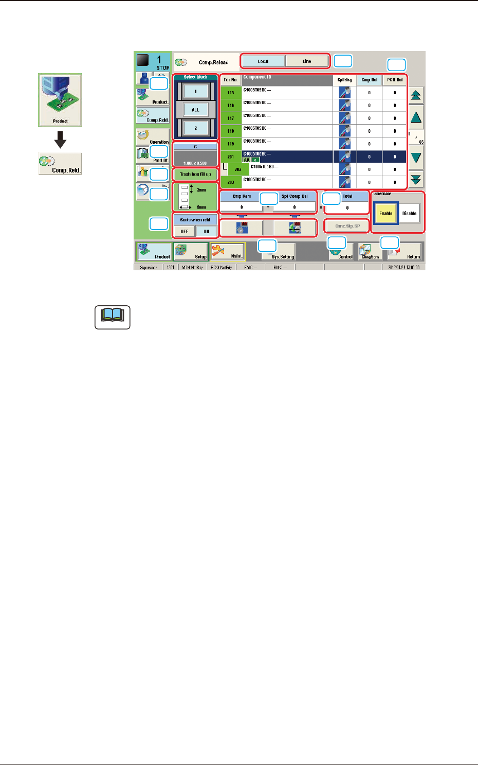
"Comp.Reload" Window F2A11
Note
The displayed contents will differ depending on selection of the options.
3. "Comp.Reload" Window
Graphic
Development
2OM-1751
1-131303-001
[1] Select block
The feeder block image is displayed.
When each block button is pressed, the "[2] List of Feeders" pane shows the
feeder information of the corresponding block.
[2] "List of Feeders" Pane
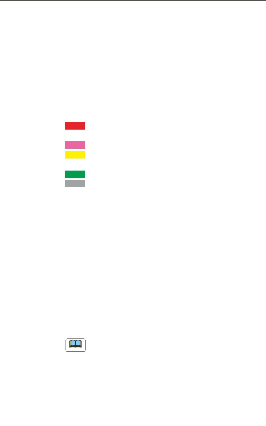
Fdr No.
The condition of each feeder is color-coded. When a component shortage
error has occurred in a feeder, the background color of the feeder No. turns
red.
According to your judgment based on the color codes, components can also
be supplied to the other feeders together with the error-caused feeder.
Red
: Feeder Unavailable (Component Shortage Error, Feeder
Not Installed, etc.)
Pink
: Splicing Stop Generated at Feeder
Yellow
: Attention Required Feeder (Warning of Component
Shortage, etc.)
Green
: The feeders are normal.
Gray
: Not selected feeder (specied as "Not Used") in the pat-
tern program
Component ID
Displayed are the component IDs.
Splicing
When the splicing function in each feeder has been enabled, it is displayed in
blue, and when the function has been disabled, it is displayed in red.
Cmp.Bal
Displayed is the number of components remaining in the feeder.
PCB.Bal
The No. of PCBs where the components can be placed before a component
shortage occurs, is displayed in these data boxes.
Note
Each button-shaped item has a button function.
When each button is pressed, the corresponding items are re-arranged in
the ascending order.
[3] Component type
Displayed are the following component data.
Comp Type
Comp Size (X, Y)
3. "Comp.Reload" Window