2OM-1751-003w_G5S.pdf - 第77页
2OM-1751 1-25 1303-001 4.1 "Run Mode" T ab Sheet [4] [Release all steps] Button When this button is pressed, all the designated steps and applied steps are cleared. [5] [Apply] Button When this button is presse…
2OM-1751
1-24
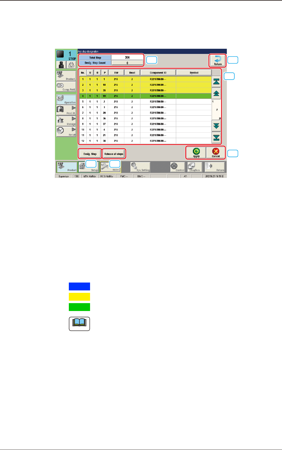
Description of "Any step designation" Window
When the [Any step designation] button is pressed in the "Semi-Auto Step Any
Desig" Window, the following window appears.
[1]
[2]
[3] [4]
[5]
[6]
F2A20
[1] No. of Total Steps and Designated Step Count Display Section
The No. of total steps and No. of designated steps are displayed in this
section.
[2] Step Display Section
The total No. of steps in the pattern program set in the machine, is displayed.
Setting the cursor on the step item in the list, designates the step. The
background color changes as follows.
Blue
:
This shows the moved step, which has not been designated.
Yellow
:
This shows the step, which has already been designated.
Green
:
This shows the step, which has been last designated.
Note
In normal cases, the starting step Nos. are displayed in the order of actual
component placement.
By pressing the [O] or the [P] button, the steps can be re-arranged in the
ascending order.
Even when the step Nos. are rearranged, the component placement order is
not changed.
[3] [Desig.Step] Button
The step No. can be entered and designate in the entry window displayed by
pressing the [Desig Step] button.
Enter the step No. in the order of "U", "O" and "P".
1303-001
4.1 "Run Mode" Tab Sheet
2OM-1751
1-251303-001
4.1 "Run Mode" Tab Sheet
[4] [Release all steps] Button
When this button is pressed, all the designated steps and applied steps are
cleared.
[5] [Apply] Button
When this button is pressed, the designated step or cleared step is applied.
[Cancel] Button
When this button is pressed, the cleared step is cancelled.
[6] [Return] Button
When this button is pressed, the "Semi-Auto Any Desig" window is returned.
Starting Procedure for the Semi-Auto Step Any Desig (free designation)
Procedure
(1) Place the PCB on the position of the step operation to be
designated.
Note
Transfer and place the PCB manually onto the aimed position.
(2) Designate the step in the "Any step designation" window and press
the [Apply] button.
Note
A dialogue "Do you save the change?" will be displayed.
Select "Yes". After the selection, the No. of designated steps is
changed.
(3) Press the [Return] button to return to the "Semi-Auto Any Desig"
window.
2OM-1751
1-261303-001
(4) When the [Start] button is selected, the designated step operation is
started.
Note
(a) Precautions during the step operation designated in "Any Step
Designation" mode.
•
The addition or deletion of step operation designated in the "Any
Step Designation" mode, is disabled. Before or after the component
placement, or after all applied steps are cancelled in the case of stop
in the course of the opeation, such addition or deletion is enabled.
•
In the case that the step designated in "Any Step Designation"
mode, is stopped in the course of the operation and the placement
is started again, the operation is started from the head of the undone
steps.
•
In the case that the operation is to be started again, after the step
designated in the "Any Step Designation" mode, is stopped in the
course of the operation and undone steps are cleared, the operation
is started from the head of the applied steps designated in "Any Step
Designation" mode.
•
Even when the PCB is discharged after the operation is stopped in
the course, the operated step data is not cleared.
(b) After all the steps are performed:
When the operation start is attempted after all the previously set steps
are performed, the component placement is not started. In order to
start the component placement, clear the previously set placement
steps.
(c) Applied Steps Clearing Procedure
Procedure
(1) Press the "Placement step clear" button in the
"Semi-Auto Any Desig" window.
(2) Press the "Release all step" button in the "Any
step designation" window and press the "Apply"
button.
(d) PCB Discharge
•
Discharge the PCB manually after all the steps designated in "Any
Step Designation" mode, are completed (including the stop in the
course of the operation).
•
Start the normal operation after the PCB discharge.
4.1 "Run Mode" Tab Sheet