2OM-1751-003w_G5S.pdf - 第78页
2OM-1751 1-26 1303-001 (4) When the [Start] button is selected, the designated step operation is started. Note (a) Precautions during the step operation designated in "Any Step Designation" mode. • The addition…
2OM-1751
1-251303-001
4.1 "Run Mode" Tab Sheet
[4] [Release all steps] Button
When this button is pressed, all the designated steps and applied steps are
cleared.
[5] [Apply] Button
When this button is pressed, the designated step or cleared step is applied.
[Cancel] Button
When this button is pressed, the cleared step is cancelled.
[6] [Return] Button
When this button is pressed, the "Semi-Auto Any Desig" window is returned.
Starting Procedure for the Semi-Auto Step Any Desig (free designation)
Procedure
(1) Place the PCB on the position of the step operation to be
designated.
Note
Transfer and place the PCB manually onto the aimed position.
(2) Designate the step in the "Any step designation" window and press
the [Apply] button.
Note
A dialogue "Do you save the change?" will be displayed.
Select "Yes". After the selection, the No. of designated steps is
changed.
(3) Press the [Return] button to return to the "Semi-Auto Any Desig"
window.

2OM-1751
1-261303-001
(4) When the [Start] button is selected, the designated step operation is
started.
Note
(a) Precautions during the step operation designated in "Any Step
Designation" mode.
•
The addition or deletion of step operation designated in the "Any
Step Designation" mode, is disabled. Before or after the component
placement, or after all applied steps are cancelled in the case of stop
in the course of the opeation, such addition or deletion is enabled.
•
In the case that the step designated in "Any Step Designation"
mode, is stopped in the course of the operation and the placement
is started again, the operation is started from the head of the undone
steps.
•
In the case that the operation is to be started again, after the step
designated in the "Any Step Designation" mode, is stopped in the
course of the operation and undone steps are cleared, the operation
is started from the head of the applied steps designated in "Any Step
Designation" mode.
•
Even when the PCB is discharged after the operation is stopped in
the course, the operated step data is not cleared.
(b) After all the steps are performed:
When the operation start is attempted after all the previously set steps
are performed, the component placement is not started. In order to
start the component placement, clear the previously set placement
steps.
(c) Applied Steps Clearing Procedure
Procedure
(1) Press the "Placement step clear" button in the
"Semi-Auto Any Desig" window.
(2) Press the "Release all step" button in the "Any
step designation" window and press the "Apply"
button.
(d) PCB Discharge
•
Discharge the PCB manually after all the steps designated in "Any
Step Designation" mode, are completed (including the stop in the
course of the operation).
•
Start the normal operation after the PCB discharge.
4.1 "Run Mode" Tab Sheet
2OM-1751
1-271303-001
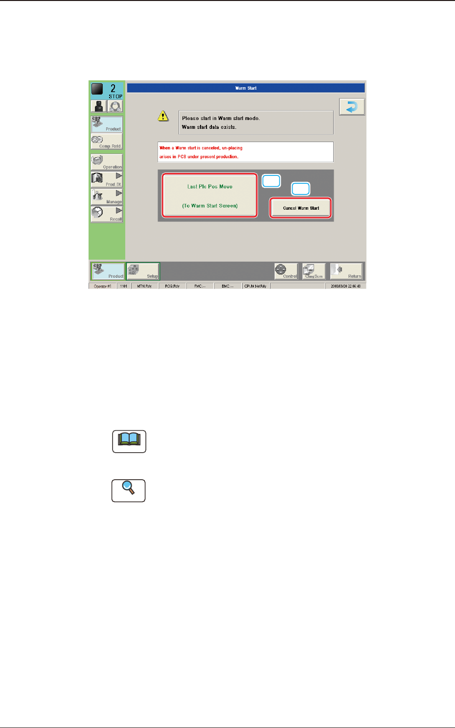
4.1.2 "Run Mode" Window ("Warm Start" Possible)
When the machine is set in the "PAUSE" mode during the automatic operation, a
warm start operation becomes possible and the "Warm Start" window appears.
[1]
[2]
F2A21
[1] [Last Plc Pos Move] Button
When this button is pressed, the "Last Placement Point Check" window is
opened.
[2] [Cancel Warm Start] Button
When pressed, the warm start is cancelled.
Note
This button is displayed only in the window for the Supervisor, When the
Warm start has been stopped, the PCB is discharged without placing any
component in the re-start operation. Pay attention to it.
Reference
Refer to "5.3 Resumption of Production through Warm Start Procedure"
(Chapter 3 in Volume 1) for the detailed information on how to execute a
warm start operation.
4.1 "Run Mode" Tab Sheet