2OM-1751-003w_G5S.pdf - 第96页
2OM-1751 1-44 1303-001 4.2 "Opr .Mode" T ab Sheet [10] Head Rotation When this button is pressed, the "Head Rotation" edit window opens. Enter the rate of speed reduction in the data entry eld for th…

2OM-1751
1-431303-001
[3] X/Y Beam
When this button is pressed, the "X/Y Beam" entry window is displayed. In
this window, set the speed reduction rate for the X/Y beam in the data entry
led.
[4] Nozzle Pickup Descent
When this button is pressed, the "Nozzle Pick-Up Descent" edit window
opens.
Set the rate of speed reduction in the data entry eld for the descending
movement of the nozzle (nozzle movement to pick up a component from the
feeder).
[5] Nozzle Pickup Ascent
When this button is pressed, the "Nozzle Pick-Up Ascent" edit window
opens.
Set the rate of speed reduction in the data entry eld for the ascending
movement of the nozzle (nozzle movement after the nozzle has picked up a
component from the feeder).
[6] Nozzle Plcmnt Descent
When this button is pressed, the "Nozzle Plcmnt Descent" edit window
opens.
Set the rate of speed reduction in the data entry eld for the descending
movement of the nozzle (nozzle movement to place a component on the
PCB).
[7] Nozzle Plcmnt Ascent
When this button is pressed, the "Nozzle Plcmnt Ascent" edit window opens.
Set the rate of speed reduction in the data entry eld for the ascending
movement of the nozzle (nozzle movement after the nozzle has placed a
component on the PCB).
[8] Nozzle Select
When this button is pressed, the "Nozzle Select" edit window opens.
Enter the rate of speed reduction in the data entry eld for a series of
operations performed when the nozzle is changed.
[9] Head Up/Down
When this button is pressed, the "Head Up/Down" edit window opens.
Enter the rate of speed reduction in the data entry eld for the head upward
and downward movement.
4.2 "Opr.Mode" Tab Sheet

2OM-1751
1-441303-001
4.2 "Opr.Mode" Tab Sheet
[10] Head Rotation
When this button is pressed, the "Head Rotation" edit window opens.
Enter the rate of speed reduction in the data entry eld for the head rotation.
Note
(a) If a higher speed than that specied in this window is set in the component
library data, it is regulated to the specied upper limit.
(b) If a lower speed than that specied in this window is set for some
components in the component library data, it becomes valid.
[11] Retention time bfr Pl descent
The stop time before the moving down for the placement, is set in this data
box.
Rang
: 0 to 255 ms
Value
: 0 ms
2OM-1751
1-451303-001
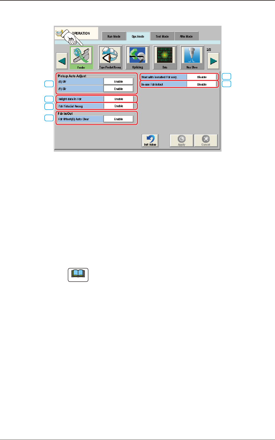
4.2.6 Feeder
[1]
[4]
[2]
[3]
[5]
[6]
F2A32
[1] Pickup Auto Adjust
This function is used to correct the feeder offset data through statistical
processing of the difference between the nozzle and component center
positions calculated during component recognition according to the
parameters specied as "Auto fdr axis adj set" in the "Auto Ope. Set-up" tab
sheet in the "System" window.
The [Enable] or the [Disable] button can be selected for the pickup auto
adjust mode.
Each button can be selected separately for the X and Y directions.
Note
The "Auto Ope. Set-up" tab appears when the [Ope. Palam.] button is
pressed after pressing the [Sys. Setting] button on the common menu bar.
4.2 "Opr.Mode" Tab Sheet