JO-072-006_w.pdf - 第105页
4-19 AKBEG-ID (16) Press the [Space] key on the keyboard or the [X/Y Measurement] button in the window to perform the measurement of the pickup position. When this operation is performed, the master tape is automatically…
4-18
AKBEG-ID
(15) Move the micrometer until the hole of the master tape is aligned with
the center of the crosshair.
As for the 8 mm feeder, it must be aligned with the pickup position on
Lane #1.
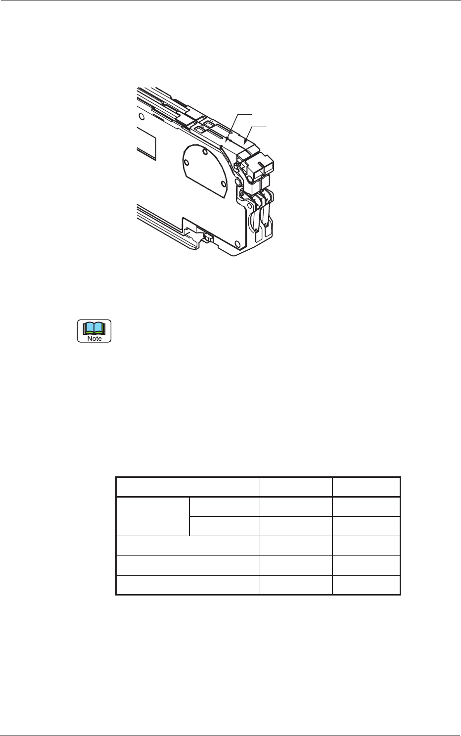
8 mm Tape Feeder
Lane #1
Lane #2
Fig. D22
The pickup position of each model is based on the X/Y coordinates of the
computer screen and almost located at the coordinates in the following
table.
Move the cursor to the position where the hole of the master tape can be
visible perfectly and perform the measurement.
As for the Y direction, the position varies by 0.5 mm (8 mm feeder) and 1
mm (12 mm or wider feeder).
Ref.:
Th
e variation occurs because the lane origin offset is set to "0" (zero)
at the measurement.
Table D5
Models X Y
G*-0808*
Lane #1 0.000 0.000
Lane #2 9.500 0.000
G*-12160 4.100
-2.00
G*-24320 -2.600 -6.000
G*-44
560 -8.600 -14
.000
0512-002
2. Feeder Measurement
4-19
AKBEG-ID
(16) Press the [Space] key on the keyboard or the [X/Y Measurement] button
in the window to perform the measurement of the pickup position.
When this operation is performed, the master tape is automatically fed
to the next pickup position after the measurement is completed.
(17) After that, align the hole of the master tape with the center of the
crosshair again.
(18) Follow the same procedure as in (16) and perform the
measurement.
(19) The measurement is repeated the specied number of times.
The defaults (measurement counts) are specied as follows.
Table D6
Models Measurement Counts
G*-0808 10 times
G*-12160 or more 9 times
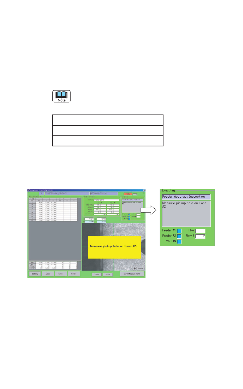
In the case of "8 mm Feeder", the following message box appears after
the measurement (repeated the above-described number of times).
Subsequently, follow the same procedure to perform the measurement
for the lane #2 side.
Fig. D24
0508-001
2. Feeder Measurement
4-20
AKBEG-ID
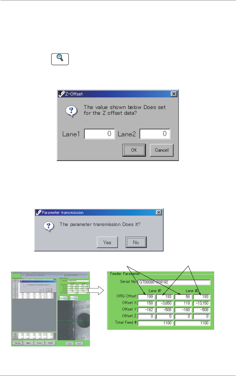
(20) After all measurements are completed, the following dialog box opens.
When it is not necessary to change the pickup height data, press the
[Cancel] button.
To change the pickup height data, enter the offset values and press the
[OK] button.
Reference
Refer to "3. Measurement of Pickup Position Height" in "Section 4" for details.
As for the models "G*-12160" or higher, the pickup height offsets are
required only for Lane #1.
Fig. D25
(21) Subsequently, the following dialog box appears.
Press the [Yes] button to transmit the results of the measurement.
Otherwise, press the [No] button.
Results of Measurement
Data before Measurement
Fig. D26
0508-001
2. Feeder Measurement