JO-072-006_w.pdf - 第41页
2-4 AKBEG-ID (4) Fasten the cables with tie wraps. Adjust the tie wraps to the location of the tie mounts and x them on the tie mounts after tightening the cable ties. Tie Mount Bundle Fig. B5 The cameral cable should a…
2-3
AKBEG-ID
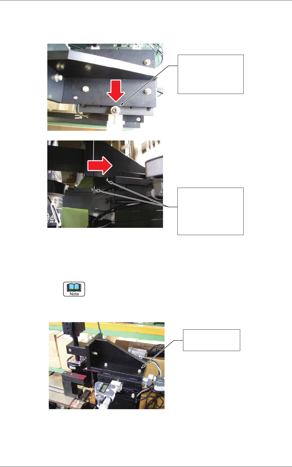
(2) Push the side face of the camera assembly against the pilot pin on the
X/Y stage and the pilot pin on the camera assembly bottom against the
side face of the X/Y stage for rm mounting.
Push the side face of
the camera assembly
against the pilot pin
on the X/Y stage.
Push the pilot pin of
the camera assembly
bottom against the
side face of the X/Y
stage.
Fig. B3
(3) After positioning, rmly tighten the four nuts (M4L20).
Tightening Torque: 3.00 to 3.66 N
•
m (30.6 to 37.4 kgf
•
cm)
After tightening the nuts, make sure that there is no clearance between the pin
and the pushed (mating) surface.
When a clearance is left, follow the above-described steps again, starting with
Step (2).
Firm Tightening of
Four Nuts (M4L20)
Fig. B4
1.1 Procedures for Attachment of Camera Unit and Detachment of Fixtures
0809-003
2-4
AKBEG-ID
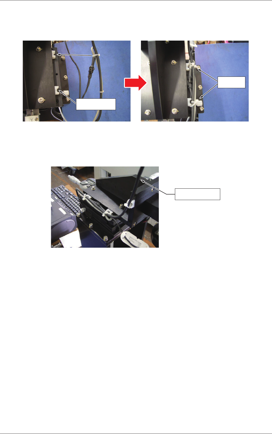
(4) Fasten the cables with tie wraps.
Adjust the tie wraps to the location of the tie mounts and x them on
the tie mounts after tightening the cable ties.
Tie Mount
Bundle
Fig. B5
The cameral cable should also be bundled and xed on the tie mounts
using the tie wraps.
Camera Cable
Fig. B6
1.1 Procedures for Attachment of Camera Unit and Detachment of Fixtures
0809-002
2-5
AKBEG-ID
1.1.3 Procedure for Detachment of Fixtures
Procedure
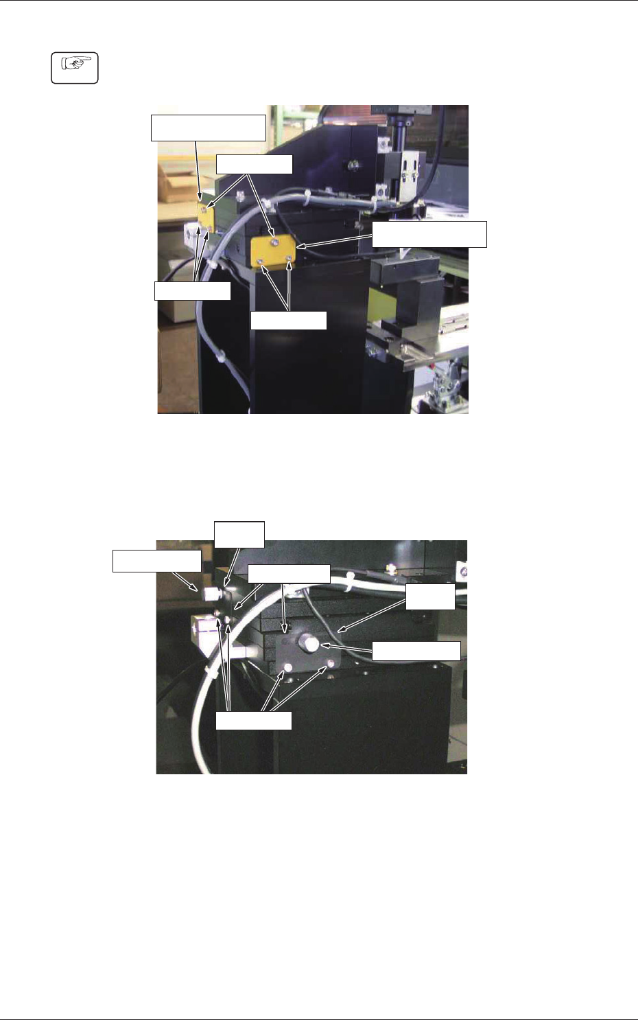
(1) Detach the xtures for both Y and X axes.
Fixture for Y Axis
Fixture for X Axis
Screw (M4)
Screw (M3)
Screw (M3)
Fig. B7
(2) Fix the clamp plate (accessory) with the screws (M3) that were used to
fasten the xtures and tighten the clamp screw for rm attachment.
X Axis
Y Axis
Clamp Screw
Clamp Screw
Clamp Plate
Screw (M3)
Fig. B8
1.1 Procedures for Attachment of Camera Unit and Detachment of Fixtures
0809-002