21 Zoll breite LP X Serie.pdf - 第16页
2 Retrofit instructions: 21" wide PCB (00176062-01 ) SIPLACE X-series Special Design 05/2006 Edition 16 2 Fig. 2.1 1 - 1 Spacer for stopper 2.6.2 Downloading the special design conveyor firmware : Use the SITEST fun…
Special Design 2 Retrofit instructions: 21" wide PCB (00176062-01) SIPLACE X-series
05/2006 Edition
15
2.6 Retrofit
2.6.1 Long board option
Installation of the Long board option is described in retrofit instructions 00193888-02. 2
: Also install the stopper spacer (00371915-xx) in placement area 2 since the fixed conveyor
side wall must be set to overwide using the SITEST function.
Setting the fixed conveyor side wall to overwide makes the space for installing the additional stop-
per for the LBO in PA2 critical. 2
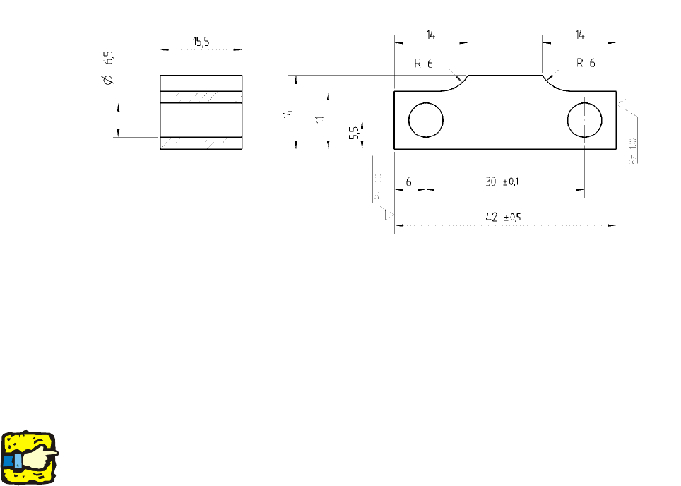
: For this reason, you should fit a spacer in order to ensure there is sufficient space for installa-
tion.
2
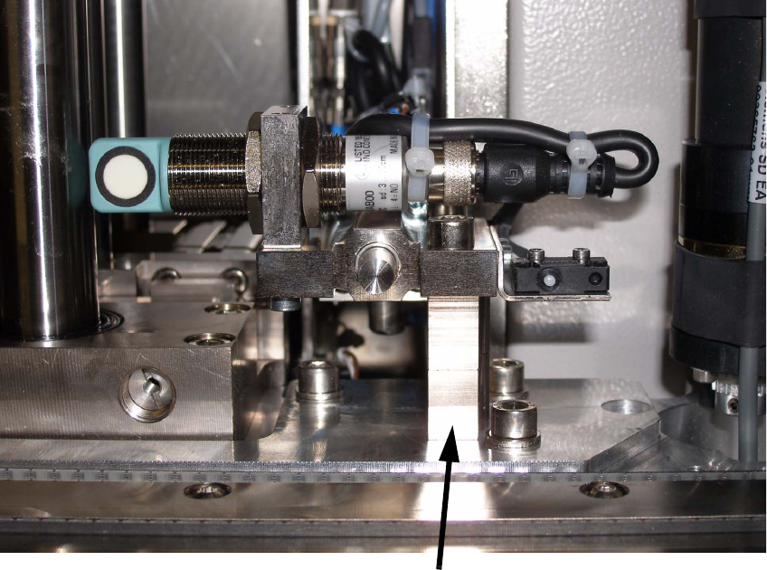
Additional spacer for stopper
2 Retrofit instructions: 21" wide PCB (00176062-01) SIPLACE X-series Special Design
05/2006 Edition
16
2
Fig. 2.11 - 1 Spacer for stopper
2.6.2 Downloading the special design conveyor firmware
: Use the SITEST function to download the special design conveyor firmware provided.
The maximum PCB width with this firmware special design is 536 mm. 2
2
Do not set the conveyor to overwide until you have downloaded the firmware. 2
2
2.6.3 Setting the conveyor
: Start the SITEST program.
: In SITEST, set the conveyor to overwide (Conveyor => Settings).
2.6.4 Measuring the PCB reference corner in placement area 1/2
Use the SITEST function to remeasure the PCB reference corners in both placement areas. 2
Special Design 2 Retrofit instructions: 21" wide PCB (00176062-01) SIPLACE X-series
05/2006 Edition
17
2.7 Description in SIPLACE Pro
SIPLACE Pro 3.1 programming system 2
There are no restrictions concerning the maximum PCB width in SIPLACE Pro. 2
The PCB can be specified if the fiducials are in the travelling range of all four (LBO) placement
areas. 2
2
2
1.) (PCB length) - 160 mm = Ymax (max. fiducial position in the Y direction) 2
2.) (PCB length) - 450 mm = Ymin (min. fiducial position in the Y direction) 2
1.) - 2.) = Location for fiducial position = 290 mm 2
2
Example: 2
PCB length = 580 mm 2
580 mm - 450 mm = 130 mm 2
580 mm - 160 mm = 420 mm 2
Ranges for defining fiducials
610 mm - (2x160 mm)= 290 mm
160
160
290
680
160
50
290
500
Range for fiducials
Y
X