00195440-05-SG_D-Series_FSE-EN.pdf - 第100页
6 Reference Run 6.1 Reference Run (D/Di- Series) 6.1.3 Axis Reference Run 100 Student Guide SIPLACE D-Series (FSE) ▪ Search for the commutation point of the X/Y axes. ▪ Position at the hardware end stopp ers. The Y gant …
6 Reference Run
6.1.3 Axis Reference Run 6.1 Reference Run (D/Di-Series)
Student Guide SIPLACE D-Series (FSE) 99
– The star axis loads the zero point correction value.
– The star axis positions itself at counter status 0. Segment 1 is now in the star pickup/placement
position.
► Z-axis reference point run
As the Z-axis does not have a zero pulse, the Z-axis end stopper is used for this "zero pulse position".
The zero point correction (ZPC) is determined during each reference run.
– The Z-axis moves again to the top end stopper and then positions itself to the standard value of 5
digits. Subsequently:
– The star axis positions to 6250 digits (6.25°).
– The Z-axis moves down again to the end stopper, transmits the Z-axis position and moves back to
the 5 digit position.
– The star axis positions to 6750 digits (6.75°).
– The Z-axis moves up again to the end stopper, transmits the Z-axis position and moves back to
the 5 digit position.
– The star axis positions to -6250 digits (-6.25°).
– The Z-axis moves down again to the end stopper, transmits the Z-axis position and moves back to
the 5 digit position.
– The star axis positions to -6750 digits (-6.75°).
– The Z-axis moves up again to the end stopper, transmits the Z-axis position and moves back to
the 5 digit position.
► The zero point correction value is calculated from the 4 Z-axis positions, is transmitted to the axis
controller and is used until the machine is switched off.
– The star axis is moved back to the 0 position (segment 1 down).
This automatic zero point correction ensures that the segment ball bearing is in the optimum position
for the circular guide.
► The head axis reference run is now finished.
6.1.3.2
6.1.3.2 Gantry Axis Reference Run
Gantry Axis Reference Run
The first reference run also includes the commutation point search for the 3-phase drive of the gantry
axes.
Sequence:
Initializing the 3-phase drive system and the position measuring system of the gantry axes:
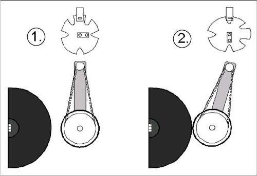
Positioning the DP axis with the help of the swivel in/out
function
Legend
1. Home position of DP drive around 1 mm away from
segment.
2. Engaged position of DP drive at segment
► DP axis reference run
– The DP station is swiveled in by a CAN bus com-
mand (2).
– The axis controller starts from the 0 position and
continues until the incremental encoder detects a
segment zero pulse.
► – The DP station is swiveled out again by a CAN bus
command (1).
6 Reference Run
6.1 Reference Run (D/Di-Series) 6.1.3 Axis Reference Run
100 Student Guide SIPLACE D-Series (FSE)
▪ Search for the commutation point of the X/Y axes.
▪ Position at the hardware end stoppers.
The Y gantry axes are stepped to the outer end stoppers.
The target position is predefined. If this is not reached and if no counter pulses can be detected at
the incremental encoder, this means that the axis has reached the hardware end stopper.
▪ Reverse direction of axis movement and search for the zero pulse on the incremental scale.
– Load the X or Y axis zero point correction.
The axis reference run is now finished and the axes can be positioned for placement operation.
Searching for the X and Y Commutation Position (A364)
A commutation position search for the 3 phases AC-drives on the gantry starts right after the head axes
reference run is succesfully finished.
1. Commutation position search during initial reference run:
Preconditions and function:
▪ Axis reference run must be successfully completed at the relevant placement heads.
▪ 2 motor phases are switched to the power supply of the servo amplifier.
▪ The 3-phase AC motor moves to the next suitable magnetic position.
▪ 2 other motor phases are switched to the servo power supply and the axis moves further.
▪ These switching steps are repeated multiple times.
The axis reference run is continued with a reference position search for the position measuring system.
Initializing the Position Measuring System
Instead of using proximity switches for the switching points, the system now searches for the hardware
end stoppers of the respective gantry axes.
▪ Positioning with small steps in the mode Standstill search
▪ Target position:
– If the target position is reached, a further step is programmed and positioned in the direction of
the end stopper.
– If the target position is not reached, the system checks whether there are any further count puls-
es are received. If none arrive over a certain period of time, the axis will recognize the reversal
point for gantry positioning and will start to search for the zero pulse.
▪ The axis positions the Y axes towards the machine center and the X axes towards the X-axis deflec-
tion bearings.
▪ The zero pulse is searched for and checked over a short travel range.
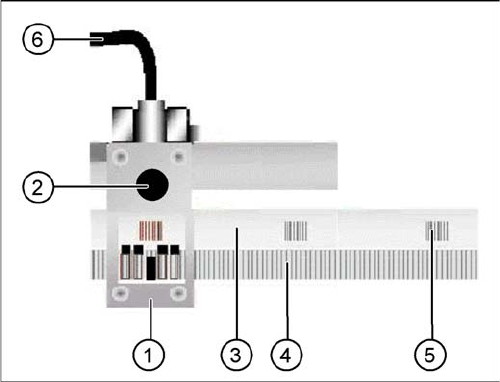
Diagram of the incremental encoder with scale
Legend
1. Incremental encoder
2. Test plug for track signals (analog)
3. Incremental scale
4. Increments on the scale (1µm resolution)
5. Zero pulse
6. Connection cable to gantry distributor/gantry head
distributor
6 Reference Run
6.1.4 Vacuum Reference Run 6.1 Reference Run (D/Di-Series)
Student Guide SIPLACE D-Series (FSE) 101
▪ The zero point correction is loaded in the position of the correct zero pulse. This ensures correct po-
sitioning in the subsequent placement operations.
6.1.4
6.1.4 Vacuum Reference Run
Vacuum Reference Run
6.1.4.1
6.1.4.1 Nozzle Cleaning, Followed by Vacuum Measurement
Nozzle Cleaning, Followed by Vacuum Measurement
The vacuum values "open" and "closed" can only be measured if the nozzles have been cleaned by air
blast to remove any contaminants.
Sequence:
► The gantry axes move the placement head to the reject position.
► The star rotates in an anticlockwise direction to move all segments through the working positions.
► The electromagnetic valve is activated in a cycle for "reject component" and "clean nozzle".
► The vacuum "open" and "closed" placement values are measured for the nozzle types.
Should an error occur, this means that the nozzle opening is too small or that the vacuum duct is
blocked. --> exchange the nozzle.
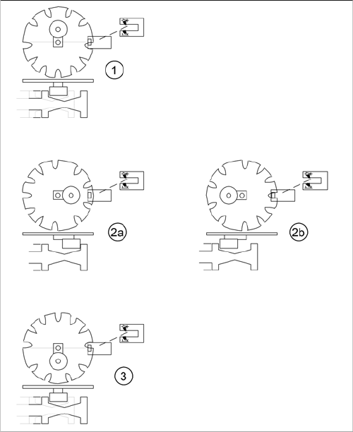
Switching over the valve positioning drives for pickup/
place and reject positions
Legend
1. Starting position. Release star axis movement.
2. 2a: The mode "Valve positioning drive pick/place" is
switched to vacuum for "nozzle open".
2b: The mode "valve positioning drive pick/place" is
switched to vacuum for "nozzle closed". Parallel to
this (diagram 2b) the "valve positioning drive reject" is
switched back to air blast (and then back again).
3. Counter position to initial position. Release star axis
movement.