00195440-05-SG_D-Series_FSE-EN.pdf - 第102页
6 Reference Run 6.1 Reference Run (D/Di- Series) 6.1.4 Vacuum Reference Run 102 Student Guide SIPLACE D-Series (FSE) 6.1.4.2 6 . 1 . 4 . 2 D e t e r m in in g t h e V a c u u m a n d T h r e s h o ld V a lu e s Determini…
6 Reference Run
6.1.4 Vacuum Reference Run 6.1 Reference Run (D/Di-Series)
Student Guide SIPLACE D-Series (FSE) 101
▪ The zero point correction is loaded in the position of the correct zero pulse. This ensures correct po-
sitioning in the subsequent placement operations.
6.1.4
6.1.4 Vacuum Reference Run
Vacuum Reference Run
6.1.4.1
6.1.4.1 Nozzle Cleaning, Followed by Vacuum Measurement
Nozzle Cleaning, Followed by Vacuum Measurement
The vacuum values "open" and "closed" can only be measured if the nozzles have been cleaned by air
blast to remove any contaminants.
Sequence:
► The gantry axes move the placement head to the reject position.
► The star rotates in an anticlockwise direction to move all segments through the working positions.
► The electromagnetic valve is activated in a cycle for "reject component" and "clean nozzle".
► The vacuum "open" and "closed" placement values are measured for the nozzle types.
Should an error occur, this means that the nozzle opening is too small or that the vacuum duct is
blocked. --> exchange the nozzle.
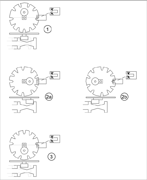
Switching over the valve positioning drives for pickup/
place and reject positions
Legend
1. Starting position. Release star axis movement.
2. 2a: The mode "Valve positioning drive pick/place" is
switched to vacuum for "nozzle open".
2b: The mode "valve positioning drive pick/place" is
switched to vacuum for "nozzle closed". Parallel to
this (diagram 2b) the "valve positioning drive reject" is
switched back to air blast (and then back again).
3. Counter position to initial position. Release star axis
movement.
6 Reference Run
6.1 Reference Run (D/Di-Series) 6.1.4 Vacuum Reference Run
102 Student Guide SIPLACE D-Series (FSE)
6.1.4.2
6.1.4.2 Determining the Vacuum and Threshold Values
Determining the Vacuum and Threshold Values
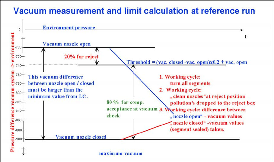
Measuring and calculating the vacuum values for a reference run
Legend
1. The vacuum is measured twice during the reference run:
– Once with closed
– and once with open valve, while air flows through the nozzle.
2. The value with closed valve depends on the ambient pressure and may vary, according to the local
weather conditions and altitude. The higher the ambient pressure, the lower the vacuum at closed
valve.
3. The value with open valve depends on the nozzle size and condition. The smaller the nozzle, the
greater the open valve value will be. A contaminated or blocked nozzle will also give a higher valve.
4. The difference between the open and closed nozzles has been preset by the line controlling line
computer (LC or SIPLACE Pro), as a minimum value. This value is different for all nozzle types e.g.
120 mbar for 914 and 904 nozzles. If these values are not achieved, the error message "Vakuum-
differenz offen-geschlossen zu gering" (vacuum difference open-closed is too low) will appear.
5. The threshold for component acceptance is also set now. In this case we have a value of 700 mbar
when the nozzle is open and a value of 900 mbar when the nozzle is closed. The calculation is per-
formed as follows:
Threshold = (900(closed) - 700(open))= x 0.2 + 700(open) = 200 x 0.2 + 700 = 740
6.1.4.3
6.1.4.3 Rotating the Nozzles into the 0 Degrees Starting Position
Rotating the Nozzles into the 0 Degrees Starting Position
While the vacuum values are being measured, the turning station can rotate all segment sleeves into the
0° starting position.
Sequence:
► The star axis rotates all segments through the working positions.
► The turning station swivels in during vacuum measurement.
► The axis controller positions the relevant segment at the light-dark transition, which represents the
0 degrees position of the sleeves. (The long side of rectangular nozzles in the X direction.)
► – The turning station is swiveled out again by a CAN bus command .
6 Reference Run
6.1.4 Vacuum Reference Run 6.1 Reference Run (D/Di-Series)
Student Guide SIPLACE D-Series (FSE) 103
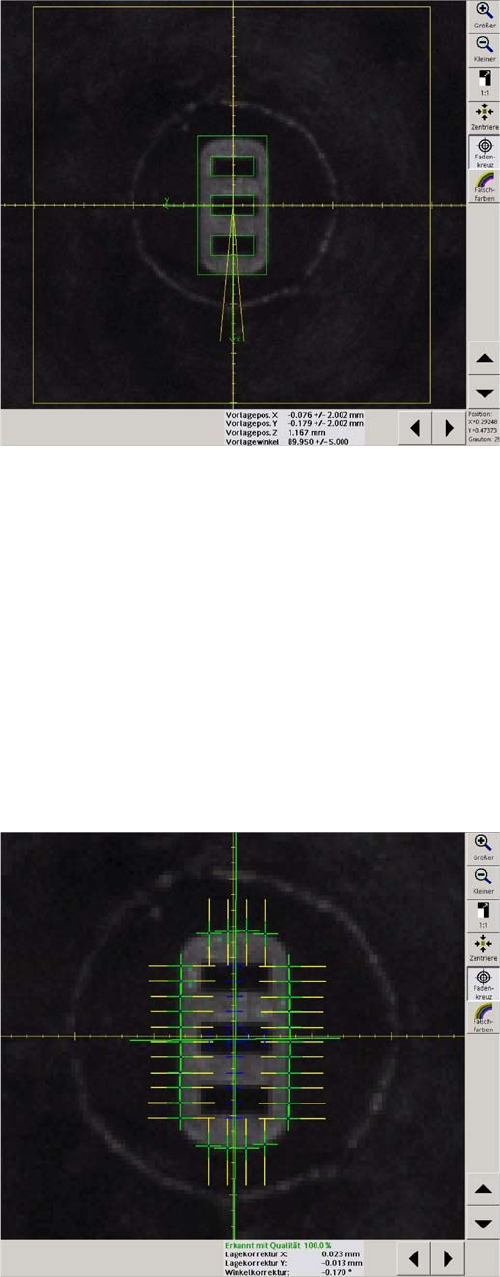
6.1.4.4
6.1.4.4 Nozzle Scanning
Nozzle Scanning
Nozzle scanning is a sight check of the nozzles to detect
contamination. The vacuum system is not used for this.
The error messages include:
Nozzle slightly dirty
Nozzle dirty
Scanning is only performed for small nozzles from 904 or
smaller. It detects bright contamination on the nozzles.
Bright contamination must be removed otherwise the fol-
lowing problems could occur as a consequence.
Placement offset
Increase rejection rates due to Vision errors (component
width/length outside the tolerance)
Impaired pickup optimization, as the component center is
incorrectly calculated.
Scanning is performed as a standard after every 350
pickup and place cycles (i.e. after 4200 components on
the 12 segment head) but only after the board has been
completed.
These settings can be programmed in the machine data
by the Siemens technician.
Sequence:
► The star axis rotates all segments through the work-
ing positions.
► The component camera illuminates the nozzle and
measures its outer and inner contours.
► If the results are out od tolerence the error message
"dirty orcomtaninated nozzle apeares.
The vacuum reference run is now finished.