00195440-05-SG_D-Series_FSE-EN.pdf - 第104页
6 Reference Run 6.1 Reference Run (D/Di- Series) 6.1.5 Height Reference Run 104 Student Guide SIPLACE D-Series (FSE) 6.1.5 6 . 1 . 5 H e ig h t R e f e r e n c e R u n Height Reference Run 6.1.5.1 6 . 1 . 5 . 1 H e a d H…
6 Reference Run
6.1.4 Vacuum Reference Run 6.1 Reference Run (D/Di-Series)
Student Guide SIPLACE D-Series (FSE) 103
6.1.4.4
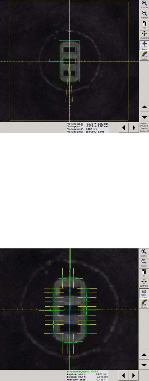
6.1.4.4 Nozzle Scanning
Nozzle Scanning
Nozzle scanning is a sight check of the nozzles to detect
contamination. The vacuum system is not used for this.
The error messages include:
Nozzle slightly dirty
Nozzle dirty
Scanning is only performed for small nozzles from 904 or
smaller. It detects bright contamination on the nozzles.
Bright contamination must be removed otherwise the fol-
lowing problems could occur as a consequence.
Placement offset
Increase rejection rates due to Vision errors (component
width/length outside the tolerance)
Impaired pickup optimization, as the component center is
incorrectly calculated.
Scanning is performed as a standard after every 350
pickup and place cycles (i.e. after 4200 components on
the 12 segment head) but only after the board has been
completed.
These settings can be programmed in the machine data
by the Siemens technician.
Sequence:
► The star axis rotates all segments through the work-
ing positions.
► The component camera illuminates the nozzle and
measures its outer and inner contours.
► If the results are out od tolerence the error message
"dirty orcomtaninated nozzle apeares.
The vacuum reference run is now finished.
6 Reference Run
6.1 Reference Run (D/Di-Series) 6.1.5 Height Reference Run
104 Student Guide SIPLACE D-Series (FSE)
6.1.5
6.1.5 Height Reference Run
Height Reference Run
6.1.5.1
6.1.5.1 Head Height Check and Nozzle Length Measurement
Head Height Check and Nozzle Length Measurement
This part of the reference run is performed in sequence at the gantries of the relevant processing area,
as the X/Y height measurement position needs to be the same for both gantries.
Sequence:
► The gantry axes move the placement head over the height measurement position on the fixed con-
veyor side.
► The Z-axis moves segment 1 down, as far as the end stopper.
► The Z.axis "height position" is read out of the Z-axis position counter.
► The Z-axis is moved up again, to the 0 position.
► This process is repeated for all the segments of the relevant placement head and then for the 2nd
gantry.
► A nozzle length error is issued if the values deviate by more than+/- 0.4 mm from the nozzle 1 meas-
urement. The nozzle causing this error must then be replaced before starting placement operations.
6.1.5.2
6.1.5.2 Nozzle Length Measurement in the Component Sensor
Nozzle Length Measurement in the Component Sensor
If the component sensor option is installed and configured on the C&P12 placement head, the MC will
issue a CAN bus command for nozzle length measurement to be performed in the component sensor,
provided the nozzle to be set up is long enough (for nozzles longer than 12 mm, appropriately longer
than a 915 nozzle).
► The shadow cast by the component sensor IR laser beam is measured during star rotation.
► The programming system prescribes the nominal parameters for dynamics, length and vacuum
checks, for the nozzle type concerned.
► The measurement is saved as the reference length for the empty nozzle.
Empty nozzles are then compared to this reference value, before the component to be checked is
taken up. A "nozzle length error in component sensor" is issued if the value deviates by +0.15/
-0.1 mm.
The whole reference run is now finished. If no error messages have been issued, the station is now ready
for placement operations. The message "Waiting for PCB in input conveyor" will be shown.
NOTICE
All measurement values are accepted for special nozzles in the X9X series.
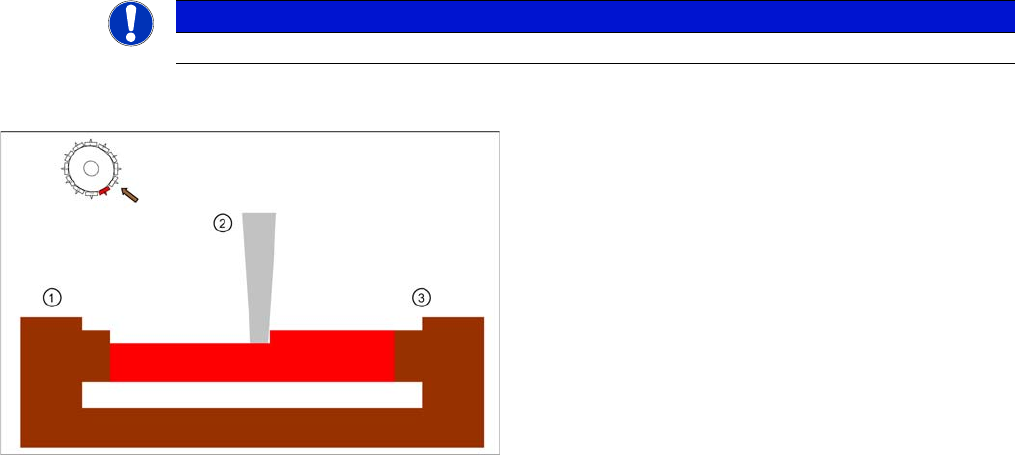
Nozzle length reference values for component recogni
-
tion in the component sensor option
Legend
1. IR receiver on C&P12 head back part
2. Nozzle
3. IR transmitter on C&P12 head front part
6 Reference Run
6.1.6 Repeating Measurement of Values During Placement 6.2 P&P Reference Run
Student Guide SIPLACE D-Series (FSE) 105
6.1.6
6.1.6 Repeating Measurement of Values During Placement
Repeating Measurement of Values During Placement
The following reference value measurements are achieved by remeasuring the reference values after
350 components have been placed per segment, at the end of PCB placement.
► Vacuum "open" and "closed" measurements
► Nozzle Scanning
► Reference nozzle length in component sensor option for C&P12 head
6.2
6.2 P&P Reference Run
P&P Reference Run
6.2.1
6.2.1 Reference run at Z axis
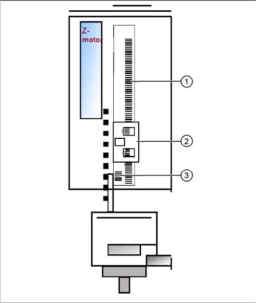
Reference run at Z axis
Reference run Z axis
Legend
1. Incremental scale mounted on moveable part of the Z
Axis
2. Fixed Incremental encoder
3. Zero puls on the incrementale scale (only one for Z
axis)
▪ Z Axis search for the commutation point of the linear
motors (in a special mode because of the danger of a
movement downwards). (A 3 phase motor continues
to run at the correct time and in the correct sequence,
when the current is switched from 1 phase to the next
one.)
▪ Then the Z Axis move upwards to the Zero pulse and
load the zero point correction.
▪ The zero point correction, max. and min. travel range,
are determined when you calibrate the head height.