00195440-05-SG_D-Series_FSE-EN.pdf - 第107页
6 Reference Run 6.2.4 Height Reference Run 6.2 P&P Reference Run Student Guide SIPLACE D-Series (FSE) 107 6.2.4 6 . 2 . 4 H e ig h t R e f e r e n c e R u n Height Reference Run Measure nozzle h eight With this funct…
6 Reference Run
6.2 P&P Reference Run 6.2.2 Reference run at D- axis
106 Student Guide SIPLACE D-Series (FSE)
6.2.2
6.2.2 Reference run at D- axis
Reference run at D- axis
6.2.3
6.2.3 Vacuum check
Vacuum check
▪ After the CAN bus processor for the vacuum/air blast distributor has booted, the vacuum/air blast
distributor is initialized. This means that vacuum/air blast generator is adjusted to ensure that neither
vacuum or air blast is generated at the nozzle.
▪ The Gantry axes move the Twin-head to the reject position.
▪ Over the reject box the Vacuum-, air blast generator switch to air blast to reject components and
check the air blast.
▪ The vacuum/air blast generator now switches over to vacuum and the open vacuum at both seg-
ments (X and D3 machine, D1/D1i: one Twin segment) is measured*.
▪ After measurement, the pressure is adjusted back to 0 bar.
▪ The vacuum reference run has now been completed for the Twin head.
* The closed vacuum value for the Twin segments relates to the calibration value which was determined
in SITEST.
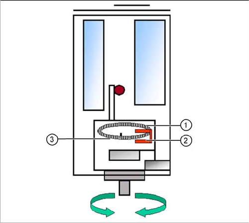
Reference run D-axis
Legend
1. Incremental glass scale D-axis
2. Incremental encoder
3. Zero pulse on the incremental glass scale
Then the D-axis (turning axis) executes the reference
run.
The D-axis runs to the zero pulse of the D- axis encoder.
The zero point correction value will be loaded. The D-axis
moves to the reference position, in accordance with the
prefix shown before the value.
Reference run completed! This is followed by the gantry
reference run (see Section Gantry).
6 Reference Run
6.2.4 Height Reference Run 6.2 P&P Reference Run
Student Guide SIPLACE D-Series (FSE) 107
6.2.4
6.2.4 Height Reference Run
Height Reference Run
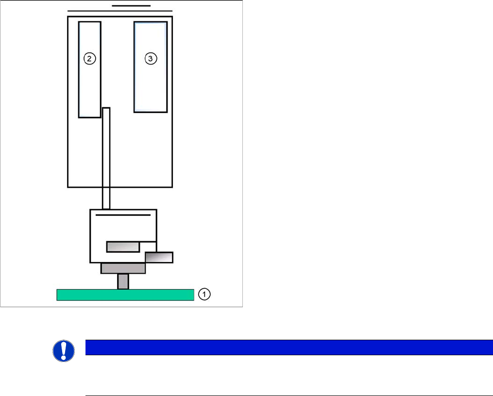
Measure nozzle height
With this function we check the correct nozzle type which
is programmed. The nozzle length is taken to calculate
the pick up and placement height for the following place-
ments.
Legend
1. Top of fixed conveyor side
2. Z motor
3. Vacuum - air blast distribution
► The gantry moves the placement heads above the
fixed conveyor side.
► The Z axis positions module 2 (X/D3 machine) down-
wards.
► The travel range of the Z axis is taken to calculate the
Twin head height in relation to the nozzle type.
► Now the same happen with module 1.
► The maximum length tolerance is 0,4 mm: If the
length difference is too high an error message is dis-
played.
NOTICE
Both modules are measured at the same position of the PCB conveyor!
This Twin head reference run is performed parallel to the C&P head reference run in the other
placement area.

6 Reference Run
6.3 Room for Your Sketches and Notes 6.2.4 Height Reference Run
108 Student Guide SIPLACE D-Series (FSE)
6.3
6.3 Room for Your Sketches and Notes
Room for Your Sketches and Notes