00195440-05-SG_D-Series_FSE-EN.pdf - 第114页
7 Axis Dynamics 7.1 Axis Dynam ic Bas ics 114 Student Guide SIPLACE D-Series (FSE) In the deceleration section, the amplitude increa ses again , to reduce the spee d of the ax is mechani cs. The freq uency is reduc ed to…
7 Axis Dynamics
7.1 Axis Dynamic Basics
Student Guide SIPLACE D-Series (FSE) 113
The overswing explained above shows that the waiting time for the overswing check starts at 13 digits
before the target area and that the end position signal is set at 5 ms after this.
The movements of approx. 6 µm which then occur can then be ignored. These do not affect the machine
or the placement process.
For assessment of the axis dynamics by a service technician, the system generates an uncommutated
current nominal signal from all motor current nominal signals. This informs you about the mechanical fric-
tion in the axis system. It can be measured on the adapter board of the axis controller or at the Vreg
output of the SIPLACE axis tester (SAT).
The uncommutated target current signal is an envelope signal for the 2 visible motor current nominal
signals from the axis controller. The missing 3rd motor current signal is calculated at the servo amplifier
board.
The known V nominal (V-target) speed signal and the force signal have been replaced by the motor cur-
rent nominal signals for DC or AC drives.
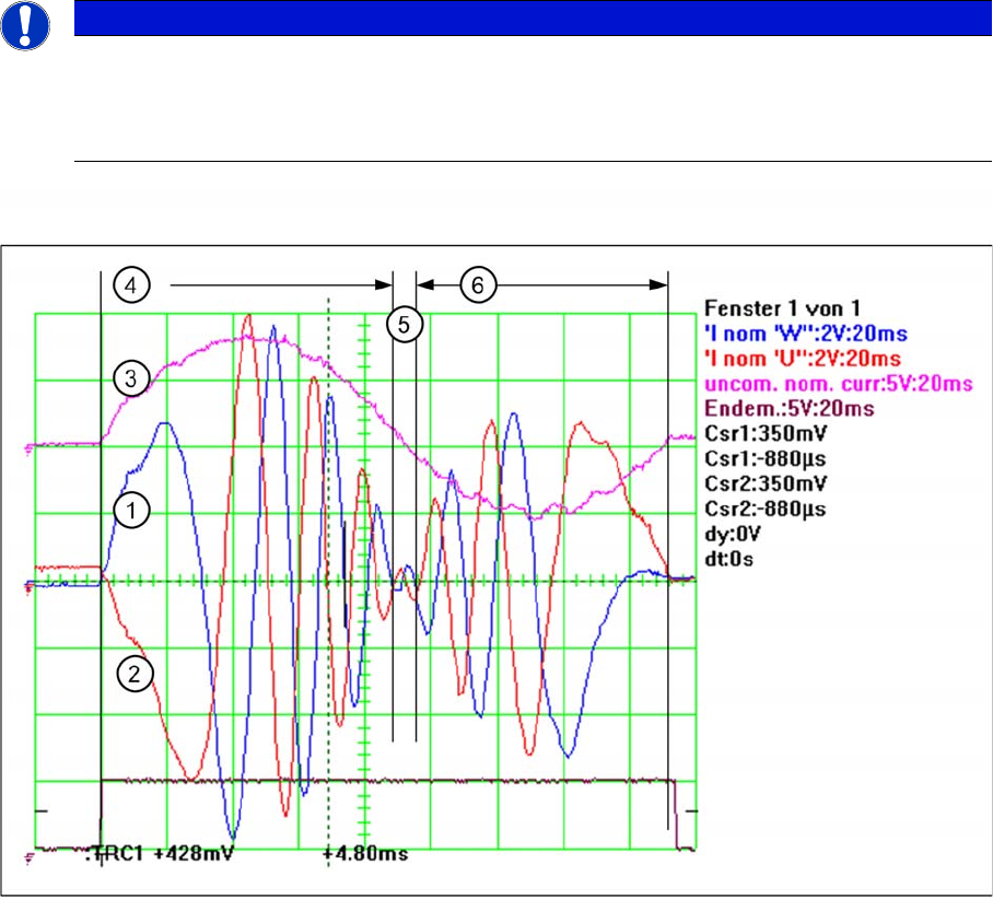
The uncommutated motor current nominal signal (3) and the motor current signals (1) (2) of an AC Motor
The acceleration section can be recognized in the motor current nominal signal of the AC motor (4), due
to the high amplitudes needed to supply the axis mechanics with sufficient force. The frequency of this
signal section is low, due to the low speed. The amplitude becomes lower and lower because the nec-
essary motor force is reduced with increasing speed.
The frequency becomes higher as the speed increases, up to a maximum frequency for maximum axis
speed (5).
NOTICE
Art und Quelle der Gefahr
These motor current signals can be measured at the V nominal and the Force output of the axis
tester. The same signals are measured at the two topmost test points of the servo amplifier
board, as Inom. U’ and Inom. W signals.
7 Axis Dynamics
7.1 Axis Dynamic Basics
114 Student Guide SIPLACE D-Series (FSE)
In the deceleration section, the amplitude increases again, to reduce the speed of the axis mechanics.
The frequency is reduced to a lower value, thereby also reducing the speed of the axis (6). Finally, the
axis is moved into the correct target position, with overshoot control.
So there is nothing to adjust all this axes have a dynamic behavior. Each axis has friction to be over-
come. The higher the friction is, the higher the amplitudes will be at acceleration and constant speed.
The higher motor force at acceleration and constant speed can be detected at the uncommutated motor
current nominal signal. Higher friction reduces the required motor force during the deceleration section,
so that the amplitude is smaller for the uncommutated motor current nominal signal.
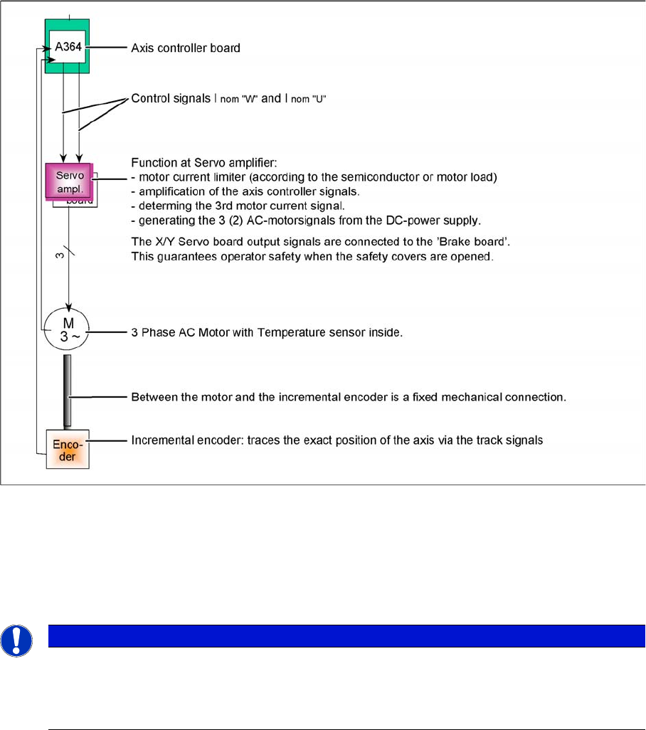
Axis block diagram example X or Y-axis of HF/Siplace X machine
Although the various axis types differ in details, all control tasks are handled by the axis controller. Two
control signals for 2 or 3 phase axis drive are transmitted to the servo. For DC drives, we use the same
hardware principle, with only one control signal to the servo amplifier. The only feedback is provided by
the track signals from the incremental encoder to the axis controller - a tacho (Z/DP axis) is not connect-
ed to the axis system.
See also
7.1 Axis Dynamic Basics [ ➙ 111]
NOTICE
Art und Quelle der Gefahr
In the case of mechanical or electrical faults, the quality of the A364 axis controller is such that
the error state from longer positioning times or signal changes will only be visible if the deviation
is very significant.
7 Axis Dynamics
7.2.1 Track Signals and Zero Pulse Signal 7.2 Position Measuring System
Student Guide SIPLACE D-Series (FSE) 115
7.2
7.2 Position Measuring System
Position Measuring System
7.2.1
7.2.1 Track Signals and Zero Pulse Signal
Track Signals and Zero Pulse Signal
Our Axes systems consists of the following parts.
▪ Axis controller for main board
▪ Servo amplifier
▪ Motor
▪ Position measuring system with incremental scale and encoder
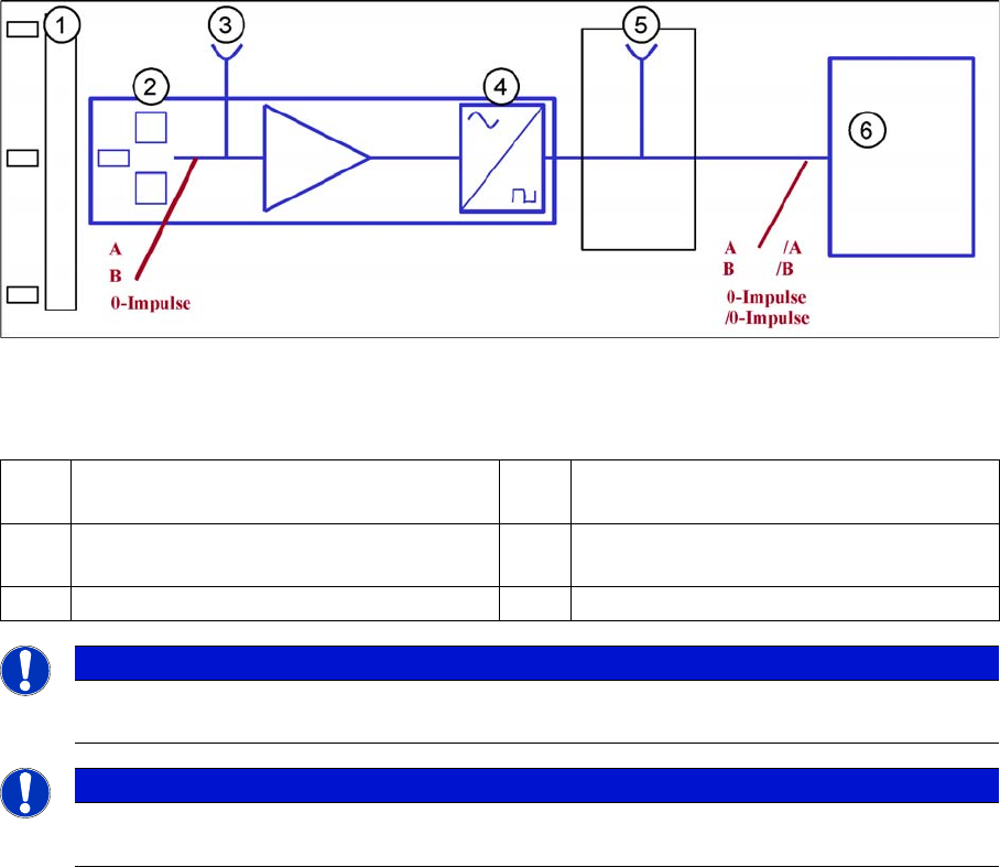
Principle circuit for position measuring systems
Legend
The axis control system with closed position control circuit determines the axis position directly, based
on the mechanical movement of the axis. The position measurement system generates analog track and
zero pulse signals during movement over the incremental scale. An amplifier, a multiplier switch and a
signal former are integrated into the incremental encoder housing. A test connector for digital signals is
either installed on the next interface board or the digital signals are measured at track A/B and the zero
pulse output of the SIPLACE axis tester. The track signals are the only feedback loops in all the axis
control systems of the SIPLACE machine. This means that each track recognition error affects the axis
control system. The gantry axes immediately stop at a fault; the head axes finish the positioning to target
before showing a track signal error.
The position is determined by a position counter on the axis controller. The moving direction of the axis
is determined by the phase shift of the track signals An advanced track A signal indicates movement to
the right, while an advanced track B signal indicates movement to the left. To make the encoder system
robust for the high resolution we multiply the frequency of the analog signal and create a high resolution
digital measuring system.
1 Incremental scale with zero pulses 4 Electronic signal multiplication and signal
digitalization
2 Incremental encoder for track A/B and zero
pulse signals (O pulse.)
5 Test output digital signals
3 Analog signal output and amplifier 6 Axis Controller
NOTICE
The incremental encoders in 1 field lens technology have the same general construction. The
transmitter and receiver of A/B count signals are located behind a common lens window.
NOTICE
This new incremental encoder supplies track signal output amplitudes of between 1.8 and
3.6 Vss, compared to the old incremental encoder which achieved a maximum value of 2.5 Vss.