00195440-05-SG_D-Series_FSE-EN.pdf - 第117页
7 Axis Dynamics 7.2.2 Zero Pulse at the Track Signal Encoder 7.2 Position Measuring System Student Guide SIPLACE D-Series (FSE) 117 Analog and digital zero pul se s i gnal (zero line set at screen c en ter) Legend At aro…
7 Axis Dynamics
7.2 Position Measuring System 7.2.2 Zero Pulse at the Track Signal Encoder
116 Student Guide SIPLACE D-Series (FSE)
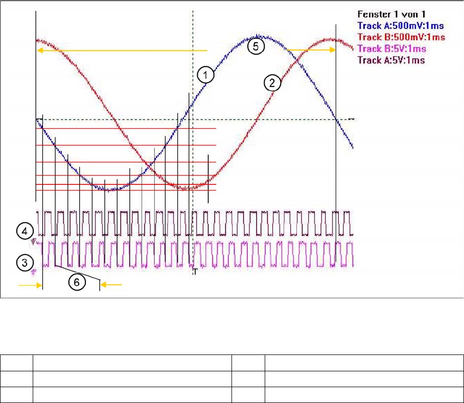
Principle signal multiplication at analog Track signals of a gantry axis
Legend
The signal multiplication can be realized as a Schmitt trigger action. During comparison of the analog
and digital axis signals, a signal multiplication of 25 (see diagram above), 10 or just 1 can be recognized.
The track signals of the C&P head axes can only be measured as digital signals i.e. The analog signals
are directly converted in the incremental encoder housing, without provision of a test connection for the
analog signals.
7.2.2
7.2.2 Zero Pulse at the Track Signal Encoder
Zero Pulse at the Track Signal Encoder
Each incremental encoder system needs initializing. This means a reference run is executed for each
axis. At the reference run the system searches for a certain position - the signal for this is the Zero pulse.
The Zero pulse is an analog signal and a ’Schmitt Trigger’ circuit digitizes it.
(Measurement of analog signal by setting the zero line at the center of the screen)
1 Analog track A signal incremental encoder 4 Digital track B signal at Test connector
2 Analog track B signal Incremental encoder 5 Period time of analog track signal
3 Digital track A signal at Test connector 6 Period time of digital track signal
7 Axis Dynamics
7.2.2 Zero Pulse at the Track Signal Encoder 7.2 Position Measuring System
Student Guide SIPLACE D-Series (FSE) 117
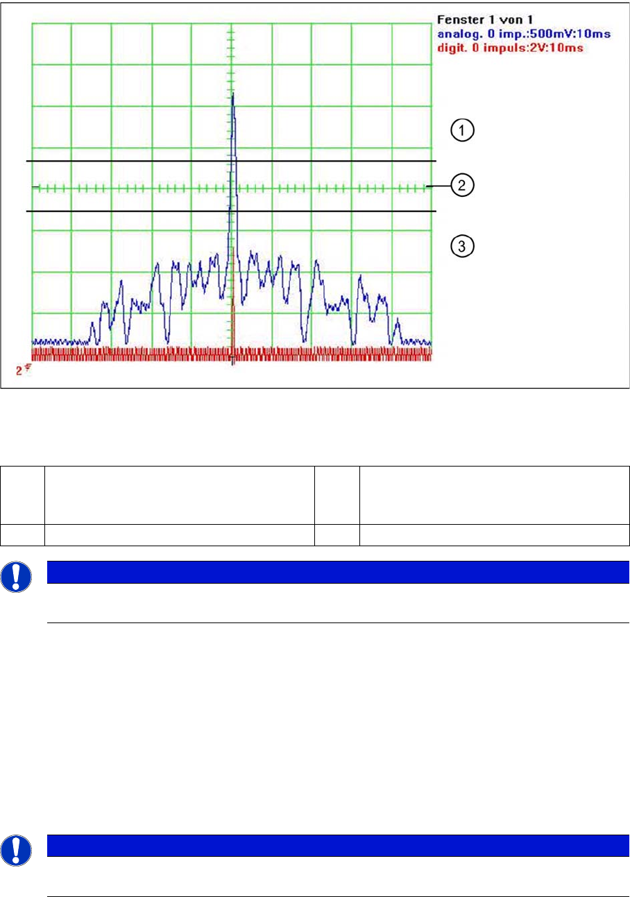
Analog and digital zero pulse signal (zero line set at screen center)
Legend
At around 2.5 V the Schmitt trigger circuit issues a brief, high pulse: the zero pulse for the position meas-
urement system. If the encoder has been installed too near to the incremental scale, one of the auxiliary
pulses could exceed the Schmitt trigger threshold and be mistakenly recognized as the zero pulse. This
would mean that the zero pulse would be recognized in the wrong position on the incremental scale. This
would then lead to a placement offset on the SIPLACE machine. The digital zero pulse is measured on
the gantry head distributor, with a probe at Pin 8 of the test connector. The inverted zero pulse can be
measured at the zero pulse output on the axis test box (or the SIPLACE AxisTester SAT).
The A364 axis controller considers all the zero pulses on the track scale i.e. even those which are re-
peated after 50 mm.
7.2.2.1
7.2.2.1 FSE Note
FSE Note
1 The analog zero pulse needs to be 0.3 V
higher than the trigger threshold for the dig-
ital zero pulse.
3 Glitches (signal noise) should not override
the limit 0,3 V less than Trigger threshold!
2 Schmitt trigger threshold
NOTICE
The A364 axis controller detects each X/Y scale zero pulse and checks the count values for
errors.
NOTICE
When using the new 1 field lens incremental encoder, the 'main peak' of the analog zero pulse
must meet the positive intersection point of the analog A/B count signals.
7 Axis Dynamics
7.3 Axis Control Assemblies 7.2.2 Zero Pulse at the Track Signal Encoder
118 Student Guide SIPLACE D-Series (FSE)
7.3
7.3 Axis Control Assemblies
Axis Control Assemblies
The control circuit for control the X- and Y-axis in general consist of the following parts:
▪ Axis board
▪ Servo board (TDS) with braking board
▪ 3-phase AB linear motor (Y-axis)/
3 phase AC (rotation) motor (X-axis)
▪ Measurement system (incremental scale and encoder (read unit))
To protect the motor of the X/Y-axes from overtemperature, these have an internal temperature sensor.
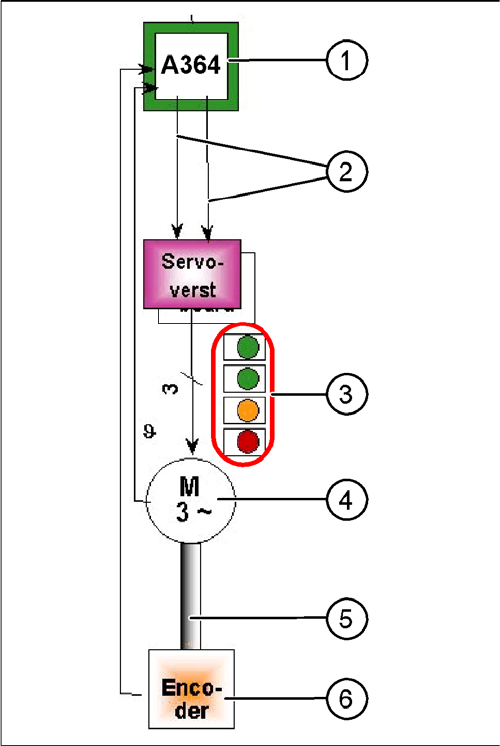
Parts "Axis control"
Legend
1. Axis Board A364
2. Control signals I
target
"W" and I
target
"U"
3. LED‘s on Servo board:
4. 3-phase AC linear motor (Y-axis) or 3-phase servo
motor with integrated temperature sensor.
5. Between motor and incremental encoder exist a fixed
mechanically connection.
6. Incremental encoder: transmit the exact position of
the axis The track signals are the only feedback sig-
nals for the axis control system.
The servo board directly controls the linear motor (inter-
mediate circuit voltage 250 V) or servo motor.