00195440-05-SG_D-Series_FSE-EN.pdf - 第119页
7 Axis Dynamics 7.3.1 Axis Controller 7.3 Axis Control Assemblies Student Guide SIPLACE D-Series (FSE) 119 7.3.1 7 . 3 . 1 A x is C o n t r o lle r Axis Controller View and test signals for A364 ax is controller of SIPLA…
7 Axis Dynamics
7.3 Axis Control Assemblies 7.2.2 Zero Pulse at the Track Signal Encoder
118 Student Guide SIPLACE D-Series (FSE)
7.3
7.3 Axis Control Assemblies
Axis Control Assemblies
The control circuit for control the X- and Y-axis in general consist of the following parts:
▪ Axis board
▪ Servo board (TDS) with braking board
▪ 3-phase AB linear motor (Y-axis)/
3 phase AC (rotation) motor (X-axis)
▪ Measurement system (incremental scale and encoder (read unit))
To protect the motor of the X/Y-axes from overtemperature, these have an internal temperature sensor.
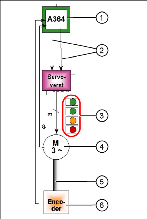
Parts "Axis control"
Legend
1. Axis Board A364
2. Control signals I
target
"W" and I
target
"U"
3. LED‘s on Servo board:
4. 3-phase AC linear motor (Y-axis) or 3-phase servo
motor with integrated temperature sensor.
5. Between motor and incremental encoder exist a fixed
mechanically connection.
6. Incremental encoder: transmit the exact position of
the axis The track signals are the only feedback sig-
nals for the axis control system.
The servo board directly controls the linear motor (inter-
mediate circuit voltage 250 V) or servo motor.
7 Axis Dynamics
7.3.1 Axis Controller 7.3 Axis Control Assemblies
Student Guide SIPLACE D-Series (FSE) 119
7.3.1
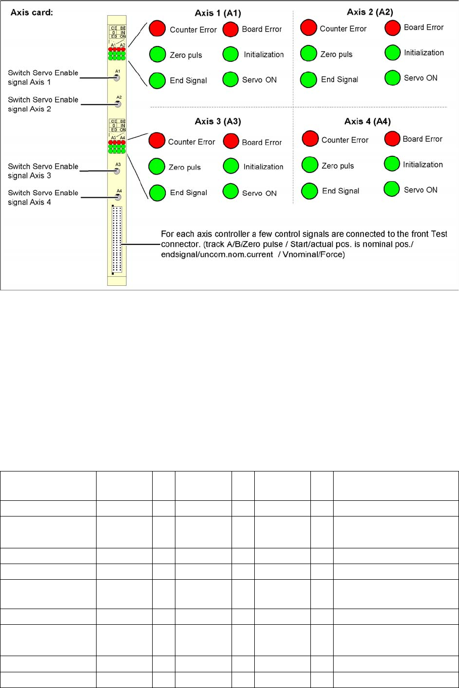
7.3.1 Axis Controller
Axis Controller
View and test signals for A364 axis controller of SIPLACE machine
The target position and start signal from the MC are transmitted to the axis controllers, which perform all
necessary calculations and controls.
The axis controller A364 in the SIPLACE machine is slot-coded. This means that no address switch
needs to be set when spare parts are replaced.
The communication and axis control functions are performed by the axis controller.
The corresponding BIOS SW and applications 1 and 2 are responsible for this.
The various drive types (motors) make different entries necessary in the control parameters. This leads
to different firmware versions for the axis types.
7.3.2
7.3.2 Axes on D/Di-Series Machine Types and Head Modularity
Axes on D/Di-Series Machine Types and Head Modularity
D4/D4i DLM Assem.1
PA1
Adr
.
Assem.2
PA1
Adr
.
Assem. 3
PA1
Adr
.
Axis type/gantry X1 0 X4 4 Free 8
Axis type/gantry Y1 1 Y4 5 Free 9 Anti-crash communication
*
1
Axis type/gantry S1 2 S4 6 DP1 10
Axis type/gantry Z1 3 Z4 7 DP4 11
Placement area 2 Assem. 1
PA2
Adr
.
Assem.2
PA2
Adr
.
Assem. 3
PA2
Adr
.
Axis type/gantry X2 16 X3 20 Free 24
Axis type/gantry Y2 17 Y3 21 Free 25 Anti-crash communication
*
1
Axis type/gantry S2 18 S3 22 DP2 26
Axis type/gantry Z2 19 Z3 23 DP3 27

7 Axis Dynamics
7.3 Axis Control Assemblies 7.3.2 Axes on D/Di-Series Machine Types and Head Modularity
120 Student Guide SIPLACE D-Series (FSE)
*
1
The two Y axes communicate directly with one another, using "anti-crash communication", via the SPI
bus (on backplane), in order to avoid crash situations.
*
2
The P&P module is a single TWIN segment on the gantry. P&P modules on dual gantry machines will
be available from April 07!! A C&P/P&P mix is also possible.
D3 DLM Assem.1
PA1
Adr
.
Assem.2
PA1
Adr
.
Assem. 3
PA1
Adr
.
Axis type/gantry X1 0 X4 4 Free 8
Axis type/gantry Y1 1 Y4 5 Free 9 Anti-crash communication
*
1
Axis type/gantry S1 2 S4 6 DP1 10
Axis type/gantry Z1 3 Z4 7 DP4 11
Placement area 2 Assem. 1
PA2
Adr
.
Assem.2
PA2
Adr
.
Assem. 3
PA2
Adr
.
Axis type/gantry X2 16 Not fitted 20 Free 24
Axis type/gantry Y2 17 Not fitted 21 Free 25
Axis type/gantry S2 18 Not fitted 22 DP2 26
Axis type/gantry Z2 19 Not fitted 23 Free 27
D3 DLM Assem.1
PA1
Adr
.
Assem.2
PA1
Adr
.
Assem. 3
PA1
Adr
.
Axis type/gantry X1 0 X4 4 Free 8
Axis type/gantry Y1 1 Y4 5 Free 9 Anti-crash communication
*
1
Axis type/gantry S1 2 S4 6 DP1 10
Axis type/gantry Z1 3 Z4 7 DP4 11
PA2 TWIN Assem. 1
PA2
Adr
.
Assem.2
PA2
Adr
.
Assem. 3
PA2
Adr
.
Axis type/gantry X2 16 Not fitted 20 Not fitted 24
Axis type/gantry Y2 17 Not fitted 21 Not fitted 25
Axis type/gantry D2 18 Not fitted 22 Not fitted 26
Axis type/gantry Z2 19 Not fitted 23 Not fitted 27
D2/D2i DLM Assem.1
PA1
Adr
.
Assem.2
PA1
Adr
.
Assem. 3
PA1
Adr
.
Axis type/gantry X1 0 X4 4 Free 8
Axis type/gantry Y1 1 Y4 5 Free 9
Axis type/gantry S1 2 S4 6 DP1 10
Axis type/gantry Z1 3 Z4 7 DP4 11
D2/D2i P&P mod-
ules *
2
Assem.1 Adr
.
Assem.2 Adr
.
Assem. 3 Adr
.
Axis type/gantry X1 0 X2 4 Not fitted
Axis type/gantry Y1 1 Y2 5 Not fitted
Axis type/gantry D 1 2 D 2 6 Not fitted
Axis type/gantry Z 1 3 Z 2 7 Not fitted