00195440-05-SG_D-Series_FSE-EN.pdf - 第122页
7 Axis Dynamics 7.3 Axis Control Assemblies 7.3.3 Servo Amplifier TBS .. and SDS ... 122 Student Guide SIPLACE D-Series (FSE) 7.3.3 7 . 3 . 3 S e r v o A m p lif ie r T B S . . a n d S D S . . . Servo Amplifier TBS .. an…

7 Axis Dynamics
7.3.2 Axes on D/Di-Series Machine Types and Head Modularity 7.3 Axis Control Assemblies
Student Guide SIPLACE D-Series (FSE) 121
*
3
Assignment deviating from standard
D1/D1i DLM/TWIN Assem.1 Adr
.
Assem.2 Assem. 3 Adr
.
Axis type/gantry X1 0 Not fitted
S1 *
3
8
Axis type/gantry Y1 1 Not fitted D1TWIN 9
Axis type/gantry
Z TWIIN *
3
2 Not fitted Free 10
Axis type/gantry
Z DLM *
3
3 Not fitted DP1DLM 11
D1/D1i single head Here TWIN Adr
.
Assem.2 Assem. 3 Adr
.
Axis type/gantry X1 0 Not fitted Not fitted 8
Axis type/gantry Y1 1 Not fitted Not fitted 9
Axis type/gantry
D Twin *
3
2 Not fitted Not fitted 10
Axis type/gantry
Z DLM *
3
3 Not fitted Not fitted 11
D1/D1i single head Here DLM Adr
.
Assem.2 Assem. 3 Adr
.
Axis type/gantry X1 0 Not fitted Free 8
Axis type/gantry Y1 1 Not fitted Free 9
Axis type/gantry
S DLM *
3
2 Not fitted Free 10
Axis type/gantry
Z DLM *
3
3 Not fitted DP DLM 11
D1/D1i end of line Assem.1 Adr
.
Assem.2 Assem. 3 Adr
.
A complete TWIN Head is
fitted here.
Axis type/gantry X1 0 Not fitted D1-2 TWIN 8
Axis type/gantry Y1 1 Not fitted D1-1 TWIN 9
Axis type/gantry Z 1-2Twin
*
3
2 Not fitted Free 10
Axis type/gantry Z 1-1 Twin
*
3
3 Not fitted Free 11
7 Axis Dynamics
7.3 Axis Control Assemblies 7.3.3 Servo Amplifier TBS .. and SDS ...
122 Student Guide SIPLACE D-Series (FSE)
7.3.3
7.3.3 Servo Amplifier TBS .. and SDS ...
Servo Amplifier TBS .. and SDS ...
Servo amplifier
The servo amplifiers of type TBS are used for the X/Y and star axes, while the SDS servo amplifier is
used for the Z and DP axes. SDS servo amplifiers can process voltages of up to 60 VDC or 120 VDC,
depending on the input.
These SDS and TBS servo amplifiers can be reset with the servo release switch on the axis controller
board.
All servos have been set to the maximum motor current of the connected drive. This means that the ser-
vo amplifiers need to be used on an axis-specific basis.
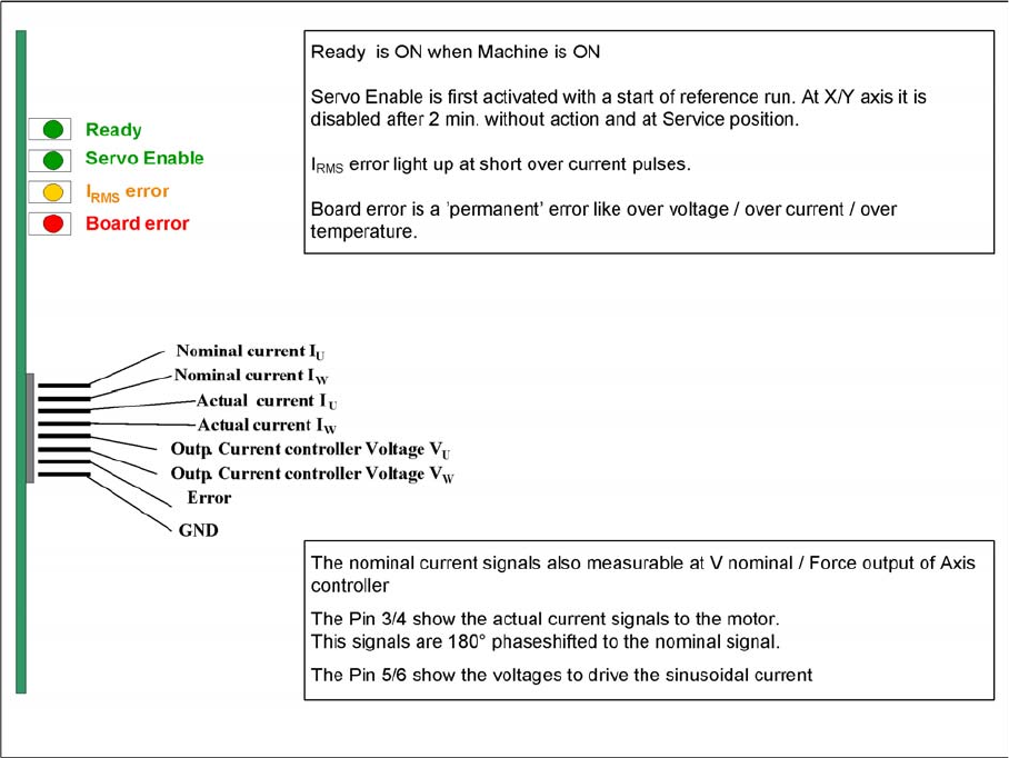
Measuring point MP7:
In the event of errors, voltages can be measured at analog output MP7 with the help of the measuring
device, to help you ascertain the cause of the error.
▪ Overvoltage -1 V
▪ Overcurrent -2 V
▪ Overtemperature -3 V
▪ Nominal current exceeded -4 V
7 Axis Dynamics
7.3.4 Overview of Axis Unit 7.3 Axis Control Assemblies
Student Guide SIPLACE D-Series (FSE) 123
7.3.4
7.3.4 Overview of Axis Unit
Overview of Axis Unit
7.3.5
7.3.5 D/Di-Series Servo Positions
D/Di-Series Servo Positions
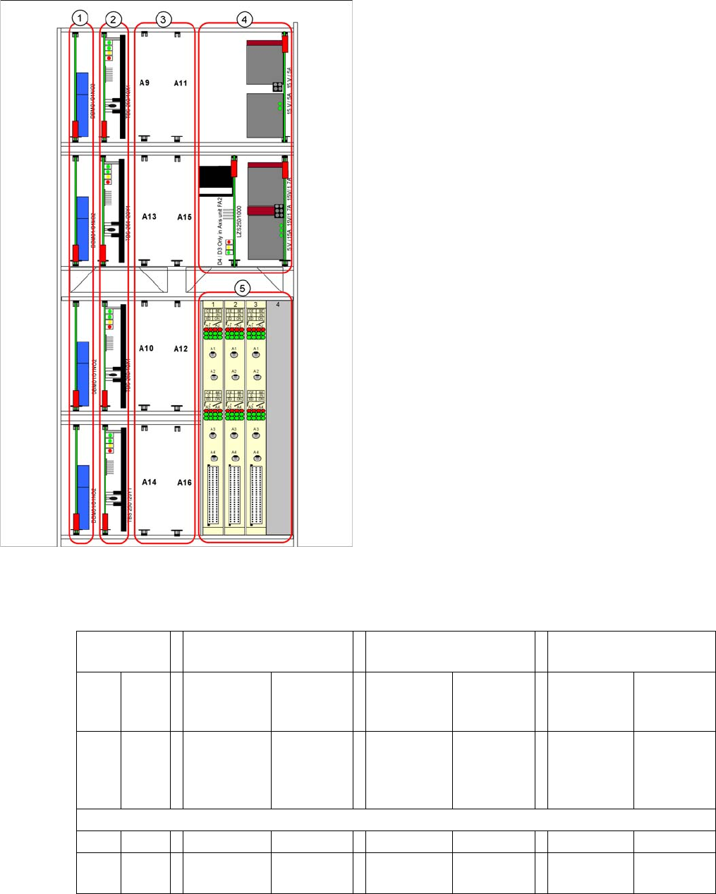
Servo positions for D1/D1i machine
Legend
1. Brake boards X/Y
2. Servo amplifier X/Y
3. Head servo positions
4. Power packs, ballast circuit (new power packs with
downwards compatibility)
5. Axis controller boards
Head servo
positions
C&P & P&P combination
at one D1/D1i gantry
/for D1/D1i single head
with C&P module
/for D1/D1i single head
with P&P module
A9 A11 SDS 60/1Z1
P&P mod-
ule.
SDS 60/
3Z1 C&P
module
--- SDS 60/
3Z1
SDS 60/1Z1
00353446-
04
---
A13 A15 SDS 60/
0.5D1 P&P
module
TBS 120/
3S1 C&P
module
--- TBS 120/
3S1
SDS 60/
0.5D1
00353447-
03
---
A10 A12 --- --- --- --- --- ---
A14 A16 SDS 60/1D1
C&P module
--- SDS 60/1D1 --- --- ---