00195440-05-SG_D-Series_FSE-EN.pdf - 第124页
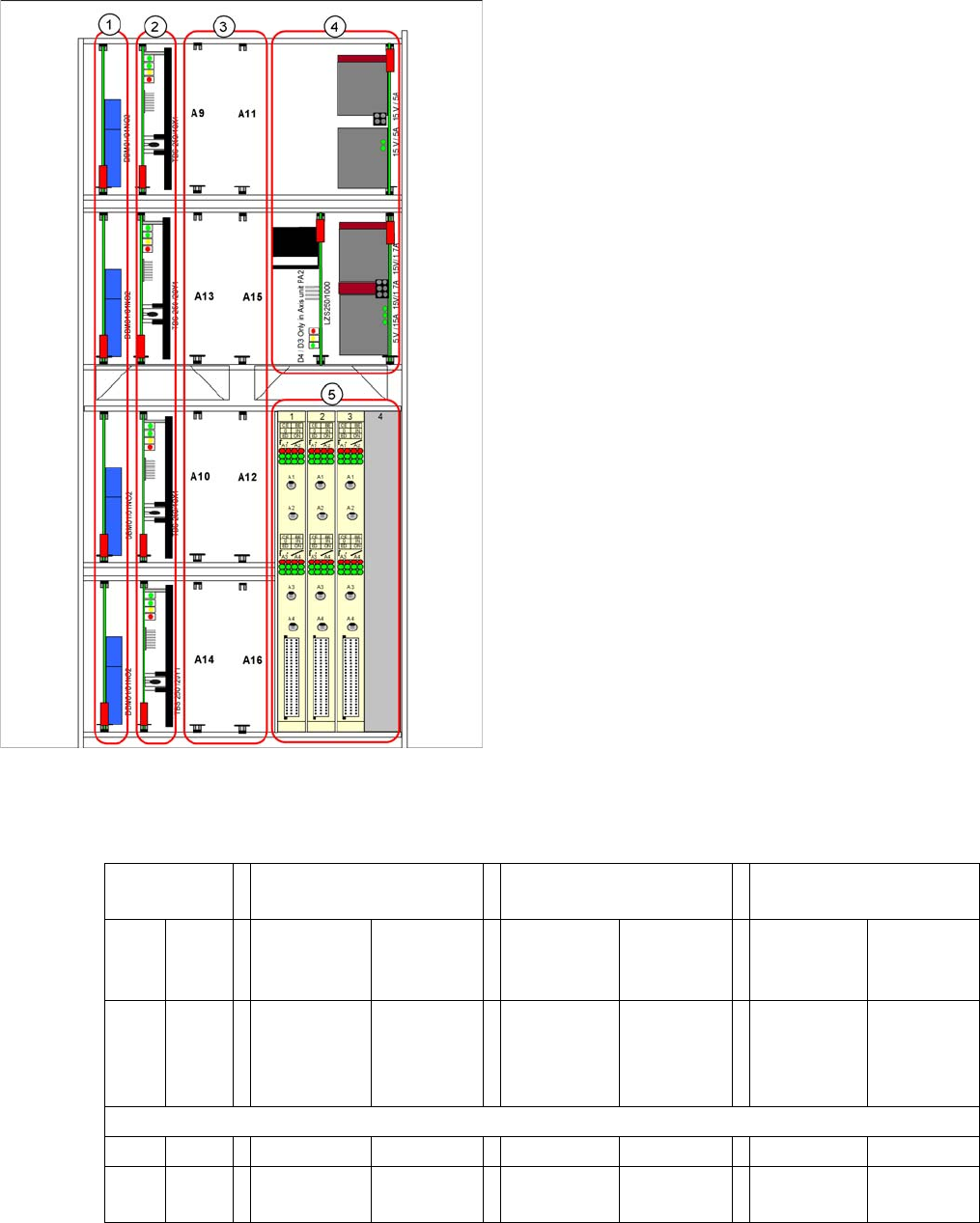
7 Axis Dynamics 7.3 Axis Control Assemblies 7.3.6 Servo Card Positions for SIPLA CE D3 124 Student Guide SIPLACE D-Series (FSE) Servo positions fo r D2/D2i machine 7.3.6 7 . 3 . 6 S e r v o C a r d P o s it io n s f o r …
7 Axis Dynamics
7.3.4 Overview of Axis Unit 7.3 Axis Control Assemblies
Student Guide SIPLACE D-Series (FSE) 123
7.3.4
7.3.4 Overview of Axis Unit
Overview of Axis Unit
7.3.5
7.3.5 D/Di-Series Servo Positions
D/Di-Series Servo Positions
Servo positions for D1/D1i machine
Legend
1. Brake boards X/Y
2. Servo amplifier X/Y
3. Head servo positions
4. Power packs, ballast circuit (new power packs with
downwards compatibility)
5. Axis controller boards
Head servo
positions
C&P & P&P combination
at one D1/D1i gantry
/for D1/D1i single head
with C&P module
/for D1/D1i single head
with P&P module
A9 A11 SDS 60/1Z1
P&P mod-
ule.
SDS 60/
3Z1 C&P
module
--- SDS 60/
3Z1
SDS 60/1Z1
00353446-
04
---
A13 A15 SDS 60/
0.5D1 P&P
module
TBS 120/
3S1 C&P
module
--- TBS 120/
3S1
SDS 60/
0.5D1
00353447-
03
---
A10 A12 --- --- --- --- --- ---
A14 A16 SDS 60/1D1
C&P module
--- SDS 60/1D1 --- --- ---

7 Axis Dynamics
7.3 Axis Control Assemblies 7.3.6 Servo Card Positions for SIPLACE D3
124 Student Guide SIPLACE D-Series (FSE)
Servo positions for D2/D2i machine
7.3.6
7.3.6 Servo Card Positions for SIPLACE D3
Servo Card Positions for SIPLACE D3
PA1: D3 head servo cards for configuration of C&P6/12 or TWIN Head at gantry 1
PA1: D3 head servo cards for configuration of C&P6/12 or TWIN Head at gantry 4
Uneven axis
servo num-
bers for first
gantry(ies) of
PA
For C&P12 For C&P6 For TWIN (next genera-
tion)
Segment 2 Segment 1
A9 A11 TBS 120/
3S1
00353445-
04
SDS 60/
3Z1
03002141-
02
TBS 120/
3S1
00353445-
04
SDS 60/
3Z1
03002141-
02
SDS 60/1Z1
00353446-
04
SDS 60/
1Z1
00353446-
04
A13 A15 --- --- --- --- SDS 60/
0.5D1
00353447-
03
SDS 60/
0.5D1
00353447-
03
No DP servo in upper
area
No DP servo in upper
area
Even axis
servo num-
bers for sec-
ond
gantry(ies+)
of PA
For C&P12 For C&P6 For TWIN
Segment 2 Segment 1
A10 A12 TBS 120/
3S1
00353445-
04
SDS 60/
3Z1
03002141-
02
TBS 120/
3S1
00353445-
04
SDS 60/
3Z1
03002141-
02
SDS 60/1Z1
00353446-
04
SDS 60/
1Z1
00353446-
04
A14 A16 SDS 60/1D1
03002142-
02
SDS 60/
1D1
03002142-
02
SDS 60/1D1
03002142-
02
SDS 60/
1D1
03002142-
02
SDS 60/
0.5D1
00353447-
03
SDS 60/
0.5D1
00353447-
03
DP servo
Gantry 'n'
DP servo
gantry 'n+'
DP servo
Gantry 'n'
DP servo
gantry 'n+'
Gantry 1 C&P6/12 TWIN Head
A 9 Star axis Z2-axis
A 11 Z-axis Z1-axis
A 13 - DP2-axis
A 15 DP axis DP1-axis
Gantry 4 C&P6/12 TWIN Head
A 10 Star axis Z2-axis
A 12 Z-axis Z1-axis
A 14 Not connected DP2-axis
A 16 DP axis DP1-axis

7 Axis Dynamics
7.4.1 Track Signals and Zero Pulse 7.4 Gantry Axis Control
Student Guide SIPLACE D-Series (FSE) 125
PA2: D3 head servo cards for configuration of C&P6/12 or TWIN Head at gantry 3
7.4
7.4 Gantry Axis Control
Gantry Axis Control
7.4.1
7.4.1 Track Signals and Zero Pulse
Track Signals and Zero Pulse
Track signals and zero pulse signals should be produced reliably by correct mechanical installation.
Should errors or malfunctions occur, check the machine as usual.
Previous incremental encoders show track A/B count signal amplitudes of 1.8 to 2.5 Vss.
New incremental encoders with 1 field optical systems have count signal amplitudes of 1.8 to 3.6 Vss.
7.4.2
7.4.2 Checking the X-Axis Dynamics
Checking the X-Axis Dynamics
7.4.2.1
7.4.2.1 Overview
Overview
The inspection of dynamics occurs with the following signals:
▪ Deviation of position
▪ Uncommutated target current value
▪ End signal ( Adapter board Axis in target position)
▪ Actual position = target position signal (trigger for position deviation)
Gantry 3 C&P6/12 TWIN Head
A 10 Star axis Z2-axis
A 12 Z-axis Z1-axis
A 14 Not connected DP2-axis
A 16 DP axis DP1-axis
NOTICE
For further details, refer to the service manual for the respective machine.
NOTICE
Before adjusting the axes, ensure that the machine has reached its operating temperature.
Switch the machine on at least 30 minutes before you begin work.