00195440-05-SG_D-Series_FSE-EN.pdf - 第125页
7 Axis Dynamics 7.4.1 Track Signals and Zero Pulse 7.4 Gantry Axis Control Student Guide SIPLACE D-Series (FSE) 125 PA2: D3 head servo cards for configuration of C&P6/12 or TWIN H ead at gantry 3 7.4 7 . 4 G a n t r …

7 Axis Dynamics
7.3 Axis Control Assemblies 7.3.6 Servo Card Positions for SIPLACE D3
124 Student Guide SIPLACE D-Series (FSE)
Servo positions for D2/D2i machine
7.3.6
7.3.6 Servo Card Positions for SIPLACE D3
Servo Card Positions for SIPLACE D3
PA1: D3 head servo cards for configuration of C&P6/12 or TWIN Head at gantry 1
PA1: D3 head servo cards for configuration of C&P6/12 or TWIN Head at gantry 4
Uneven axis
servo num-
bers for first
gantry(ies) of
PA
For C&P12 For C&P6 For TWIN (next genera-
tion)
Segment 2 Segment 1
A9 A11 TBS 120/
3S1
00353445-
04
SDS 60/
3Z1
03002141-
02
TBS 120/
3S1
00353445-
04
SDS 60/
3Z1
03002141-
02
SDS 60/1Z1
00353446-
04
SDS 60/
1Z1
00353446-
04
A13 A15 --- --- --- --- SDS 60/
0.5D1
00353447-
03
SDS 60/
0.5D1
00353447-
03
No DP servo in upper
area
No DP servo in upper
area
Even axis
servo num-
bers for sec-
ond
gantry(ies+)
of PA
For C&P12 For C&P6 For TWIN
Segment 2 Segment 1
A10 A12 TBS 120/
3S1
00353445-
04
SDS 60/
3Z1
03002141-
02
TBS 120/
3S1
00353445-
04
SDS 60/
3Z1
03002141-
02
SDS 60/1Z1
00353446-
04
SDS 60/
1Z1
00353446-
04
A14 A16 SDS 60/1D1
03002142-
02
SDS 60/
1D1
03002142-
02
SDS 60/1D1
03002142-
02
SDS 60/
1D1
03002142-
02
SDS 60/
0.5D1
00353447-
03
SDS 60/
0.5D1
00353447-
03
DP servo
Gantry 'n'
DP servo
gantry 'n+'
DP servo
Gantry 'n'
DP servo
gantry 'n+'
Gantry 1 C&P6/12 TWIN Head
A 9 Star axis Z2-axis
A 11 Z-axis Z1-axis
A 13 - DP2-axis
A 15 DP axis DP1-axis
Gantry 4 C&P6/12 TWIN Head
A 10 Star axis Z2-axis
A 12 Z-axis Z1-axis
A 14 Not connected DP2-axis
A 16 DP axis DP1-axis

7 Axis Dynamics
7.4.1 Track Signals and Zero Pulse 7.4 Gantry Axis Control
Student Guide SIPLACE D-Series (FSE) 125
PA2: D3 head servo cards for configuration of C&P6/12 or TWIN Head at gantry 3
7.4
7.4 Gantry Axis Control
Gantry Axis Control
7.4.1
7.4.1 Track Signals and Zero Pulse
Track Signals and Zero Pulse
Track signals and zero pulse signals should be produced reliably by correct mechanical installation.
Should errors or malfunctions occur, check the machine as usual.
Previous incremental encoders show track A/B count signal amplitudes of 1.8 to 2.5 Vss.
New incremental encoders with 1 field optical systems have count signal amplitudes of 1.8 to 3.6 Vss.
7.4.2
7.4.2 Checking the X-Axis Dynamics
Checking the X-Axis Dynamics
7.4.2.1
7.4.2.1 Overview
Overview
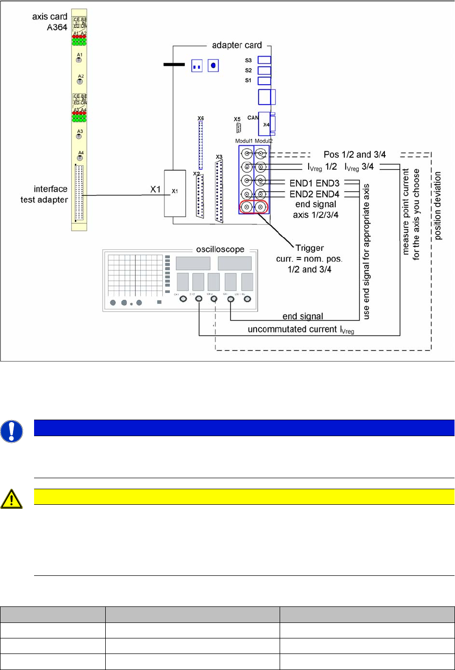
The inspection of dynamics occurs with the following signals:
▪ Deviation of position
▪ Uncommutated target current value
▪ End signal ( Adapter board Axis in target position)
▪ Actual position = target position signal (trigger for position deviation)
Gantry 3 C&P6/12 TWIN Head
A 10 Star axis Z2-axis
A 12 Z-axis Z1-axis
A 14 Not connected DP2-axis
A 16 DP axis DP1-axis
NOTICE
For further details, refer to the service manual for the respective machine.
NOTICE
Before adjusting the axes, ensure that the machine has reached its operating temperature.
Switch the machine on at least 30 minutes before you begin work.
7 Axis Dynamics
7.4 Gantry Axis Control 7.4.2 Checking the X-Axis Dynamics
126 Student Guide SIPLACE D-Series (FSE)
7.4.2.2
7.4.2.2 Measurement Setup with Adapter Board for A364
Measurement Setup with Adapter Board for A364
Measurement setup with axis test box
▪ Additional connection at channel 4 could be the actual position = target position signal from trigger
m1/2 of the adapter board or the position deviation.
7.4.2.3
7.4.2.3 Switches and Switch Settings
Switches and Switch Settings
NOTICE
Measure the signals directly on the adapter board!
The position deviation emitted there offers the advantage of showing the actual axis controller
function.
CAUTION
When checking the dynamics, it may be sufficient if you check the travel times and overshoot
behavior of the axis with the SIPLACE axis tester (SAT) display and the values in the settings
tables.
However, when checking for errors, you will need to use a suitable oscilloscope for the dynam-
ics analysis.
Switches Top switch position Bottom switch position
S3 none none
S2 Signals from axis controller 3 (A3) Signals from axis controller 4 (A4)
S1 Signals from axis controller 1 (A1) Signals from axis controller 2 (A2)