00195440-05-SG_D-Series_FSE-EN.pdf - 第127页
7 Axis Dynamics 7.4.2 Checking the X-Axis Dynamics 7.4 Gantry Axis Co ntrol Student Guide SIPLACE D-Series (FSE) 127 7.4.2.4 7 . 4 . 2 . 4 X - a x is T r a v e l P r o f ile s f o r C & P 1 2 X-axis Travel Profiles f…
7 Axis Dynamics
7.4 Gantry Axis Control 7.4.2 Checking the X-Axis Dynamics
126 Student Guide SIPLACE D-Series (FSE)
7.4.2.2
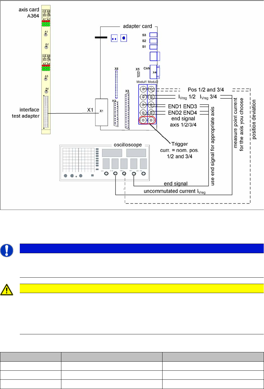
7.4.2.2 Measurement Setup with Adapter Board for A364
Measurement Setup with Adapter Board for A364
Measurement setup with axis test box
▪ Additional connection at channel 4 could be the actual position = target position signal from trigger
m1/2 of the adapter board or the position deviation.
7.4.2.3
7.4.2.3 Switches and Switch Settings
Switches and Switch Settings
NOTICE
Measure the signals directly on the adapter board!
The position deviation emitted there offers the advantage of showing the actual axis controller
function.
CAUTION
When checking the dynamics, it may be sufficient if you check the travel times and overshoot
behavior of the axis with the SIPLACE axis tester (SAT) display and the values in the settings
tables.
However, when checking for errors, you will need to use a suitable oscilloscope for the dynam-
ics analysis.
Switches Top switch position Bottom switch position
S3 none none
S2 Signals from axis controller 3 (A3) Signals from axis controller 4 (A4)
S1 Signals from axis controller 1 (A1) Signals from axis controller 2 (A2)
7 Axis Dynamics
7.4.2 Checking the X-Axis Dynamics 7.4 Gantry Axis Control
Student Guide SIPLACE D-Series (FSE) 127
7.4.2.4
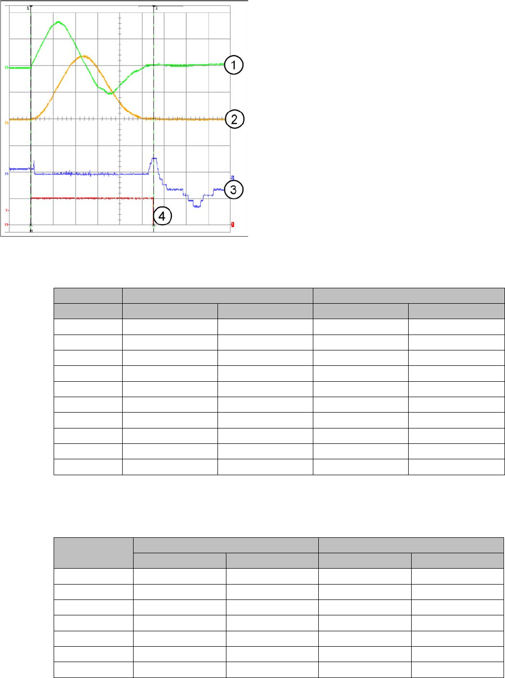
7.4.2.4 X-axis Travel Profiles for C&P12
X-axis Travel Profiles for C&P12
7.4.2.5
7.4.2.5 X-Axis Travel Time Table (D1/D2/D1i/D2i)
X-Axis Travel Time Table (D1/D2/D1i/D2i)
7.4.2.6
7.4.2.6 X-Axis Travel Time Table (D3)
X-Axis Travel Time Table (D3)
In software version 603 the gantry travel times for the C&P head are about 5 ms faster than before:
Travel times with 603 for X gantry axis, with the various different head configurations
X-axis signal path for 15000 digit path
Legend
1. Uncommutated current signal V
reg
2. Speed signal (Vnominal – currently not supported)
3. Deviation of position
4. End signal
Distance: 15mm = 15000 Digit
Time: 56 +/-5ms
D1/D1i machine: C&P6 or C&P12 + P&P D2/D2i machine: C&P6 or C&P12
Range / digit Target time / ms Tolerance /ms Target time / ms Tolerance /ms
500 30 +/-5 33 +/-5
1000 33 +/-5 35 +/-5
2000 39 +/-5 37 +/-5
5000 48 +/-5 43 +/-5
15000 60 +/-5 56 +/-5
20000 66 +/-10 64 +/-10
50000 95 +/-10 88 +/-10
100000 126 +/-10 117 +/-10
200000 174 +/-15 159 +/-15
300000 214 +/-15 199 +/-15
Range / digit X gantry axis (C&P6, C&P12) X gantry axis with Twin head
Target time / ms Tolerance /ms Target time / ms Tolerance /ms
50021+/-525+/-5
1000 24 +/-5 28 +/-5
2000 30 +/-5 34 +/-5
5000 42 +/-5 41 +/-5
15000 53 +/-5 54 +/-5
20000 59 +/-5 59 +/-5
50000 82 +/-10 87 +/-10
7 Axis Dynamics
7.4 Gantry Axis Control 7.4.3 Checking the Y-Axis Dynamics
128 Student Guide SIPLACE D-Series (FSE)
7.4.2.7
7.4.2.7 X-Axis Travel Time Table (D4/D4i)
X-Axis Travel Time Table (D4/D4i)
7.4.3
7.4.3 Checking the Y-Axis Dynamics
Checking the Y-Axis Dynamics
7.4.3.1
7.4.3.1 Measurement Setup
Measurement Setup
See also
7.4.2 Checking the X-Axis Dynamics [ ➙ 125]
7.4.3.2
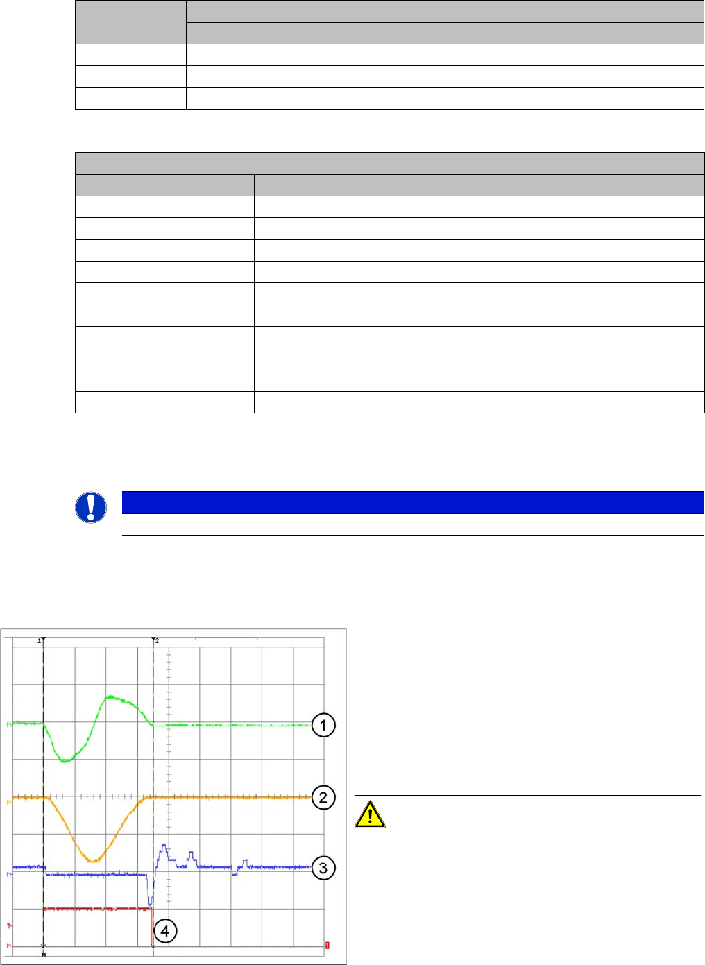
7.4.3.2 Y-Axis Travel Profiles for C&P12
Y-Axis Travel Profiles for C&P12
100000 121 +/-10 125 +/-10
200000 169 +/-10 170 +/-10
300000 208 +/-15 209 +/-15
Range / digit X gantry axis (C&P6, C&P12) X gantry axis with Twin head
Target time / ms Tolerance /ms Target time / ms Tolerance /ms
X-axis gantry axis with DLM2 (C&P12)
Range / digit Target time / ms Tolerance /ms
500 32 +/-5
1000 34 +/-5
2000 38 +/-5
5000 45 +/-5
15000 56 +/-5
20000 63 +/-5
50000 87 +/-10
100000 114 +/-10
200000 162 +/-10
300000 205 +/-15
NOTICE
The measurement procedure is prepared and performed identically to that for the X-axis
Y-axis signal path for 15000 digit path
Legend
1. Uncommutated current signal V
reg
2. Speed signal (Vnominal – currently not supported)
3. Deviation of position
4. End signal
Distance: 15mm = 15000 Digit
Time: 70 +/-5ms
CAUTION! The permissible position deviation
for placement with C&P12: 10 µm (digits)