00195440-05-SG_D-Series_FSE-EN.pdf - 第136页
8 Gantry 8.2 Overall Gantry Design 8.1.3 Y-Axis Mechanical Structure 136 Student Guide SIPLACE D-Series (FSE) Overall Gantry Design Assembly D4/D4i D3 D2/D2i D1/D1i D1/D1i single head Gantry Cast gantry HS CFK06 gant ry …
8 Gantry
8.1.3 Y-Axis Mechanical Structure 8.2 Overall Gantry Design
Student Guide SIPLACE D-Series (FSE) 135
of Mechanical Layout
With the help of a tooth Mechanical Layout rotary movement of the X-axis motor is directly converted
into a lengthwise movement of the placement head, in the X-direction.
The linear guide rails under the X-axis guide the head assembly plate and the placement head along the
X-axis.
The X-motor is cooled by a fan at the Y-axis pickup position and the motor temperature is also monitored
by a sensor.
8.1.3
8.1.3 Y-Axis Mechanical Structure
Y-Axis Mechanical Structure
Mechanical axis structure – part 2 - view from below (D4/D4i shown as example)
Legend
of Mechanical Layout
A line Mechanical Layout the entire gantry (X-axis, head assembly plate and placement head) in the Y-
axis direction. This linear motor consists of a primary and secondary part. The secondary part consists
of permanent magnets, which are fastened lengthwise (Y direction) to the machine frame.
The primary part consists of inductors (motor windings), which are directly fastened to the gantry, in a
casing.
The drive is cooled by the compressed air supply to the placement head and also has integrated tem-
perature sensors, which are monitored by the axis controller.
8.2
8.2 Overall Gantry Design
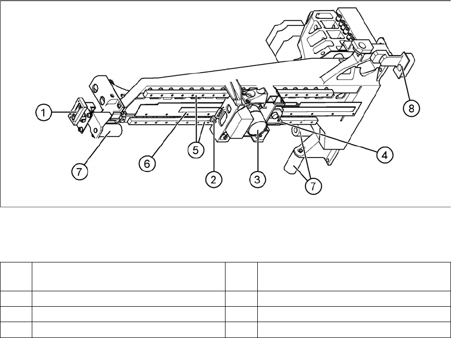
Overall Gantry Design
The gantries on the 4 machine types in the D/Di-series have the following common/different features:
1 Y brake 5 2x linear guide rails, each with a linear
bearing
2 X brake 6 X-axis incremental scale
3 Digital PCB camera (shape varies) 7 Elastomeric spring 25x10.5x50
4 X-axis incremental encoder 8 Y-axis incremental encoder

8 Gantry
8.2 Overall Gantry Design 8.1.3 Y-Axis Mechanical Structure
136 Student Guide SIPLACE D-Series (FSE)
Overall Gantry Design
Assembly D4/D4i D3 D2/D2i D1/D1i D1/D1i single
head
Gantry Cast gantry
HS
CFK06 gantry
X3
Extended cast gantry
X-drive Motor with belt
drive
Linear motor Motor with belt drive
X-motor cooling
(filter mats!!)
100/120 mm
fan in Y-axis
pickup posi-
tion
Exhaust for
vacuum distri-
bution
120 mm fan in
Y-axis pickup
position, C&P
head to MA
center
120 mm fan in
Y-axis pickup
position, C&P
head on the
right in each
case
120 mm fan in
Y-axis pickup
position
C&P head
(right) P&P
head (left)
Temperature
sensor integrat-
ed into motor
Cable to axis controller
X belt tension 53 Hz +1 /-3 --- 44 Hz +/-1
Incremental en-
coder
With optical 1-field technology
Incremental
scale
Glued on met-
al strips and
screwed to
gantry
Glued on an
aluminum strip
with edge
guide. This is
glued onto CFK
material
Glued on gantry
X-axis travel
ranges (to bump-
er)
373.5 mm ~480 mm 473.5 mm
X-axis incremen-
tal scale length
440 510 500
Arrangement of
bearing slider
1 slider on
each of the 2
linear guides,
side by side
2 sliders on
each of the 2
linear guides,
one above the
other
1 slider on each of the 2 linear guides, side by side
Slider for X linear
guidance
Do NOT grease
Placement
head(s)
4 C&P12 C&P12/6 and/
or 1 TWIN
2 C&P12 or
C&P6 or mixed
CP12 or 6 and 1
P&P module
C&P 12 or 6 or
P&P module
Head mount with Gantry head
distributor
board carrier
X motor with
board carrier
Gantry head distributor board carrier
PCB camera
SST34
Below gantry
Y drive Linear motor
Y-motor cooling Compressed
air supply to
head
Fan in pneu-
matic rack
Compressed air supply to head
Temperature
sensor integrat-
ed into motor
Wiring to axis controller

8 Gantry
8.1.3 Y-Axis Mechanical Structure 8.2 Overall Gantry Design
Student Guide SIPLACE D-Series (FSE) 137
Incremental en-
coder
With optical 1-field technology
Incremental
scale
Glued to MA
frame. Gauge
set HS
Glued to MA
frame. Gauge
set HF
Glued to MA frame. Gauge set NEW
Y travel range
(per gantry and
up to stopper or
2nd gantry)
~1507.5 mm ~1234.0 mm
(gantry 2)
~1428.5 mm
(gantry 1)
~1205 mm ~1591.5 mm
Y incremental
scale length per
PA
1600 mm 1960 mm (as in
X machine)
1960 mm (as in X machine)
Arrangement of
bearing slider
2 sliders on each of the 2 linear guides, one above the other
Y linear guid-
ance slider
Grease
Temperature
sensors for com-
pensation
1 at each gan-
try
2 at each gantry 1 at each gantry
X-axis distribu-
tor board
Gantry head
distributor,
version 3
Head interface
and head
adapter
Gantry head distributor, version 3
Compressed air
distributor block
Yes, with di-
rect tubes to
head
Yes, X version Yes, with tubes
to T-piece and
then to head
Yes, with tubes
to T-piece and
then to heads
Yes, with tubes
to T-piece, 1
output blocked
Y-axis distribu-
tor board
Gantry distrib-
utor
Gantry inter-
face
Gantry distributor
End position
proximity switch
None
Light barrier for
anti-crash moni-
toring
Not any more Never needed
Anti-Crash
Board
Not any more
NOTICE
eSW axis controller
All zero pulses for the gantry axes are checked to see whether 50,000 count pulses occur or
whether a whole number multiple of this occurs!!
An overshoot check for gantry axis positioning is no longer required. The continual calculation
of the axis positioning, based on the axis track signals, gives optimal positioning, even in the
case of mechanical defects.
Travel range: axis controller determines hardware position at stopper; 2 mm before; travel
range – software position – 0.5 (X) 1.5 mm (Y) before that - limited.
Assembly D4/D4i D3 D2/D2i D1/D1i D1/D1i single
head