00195440-05-SG_D-Series_FSE-EN.pdf - 第137页
8 Gantry 8.1.3 Y-Axis Mechanical Structure 8.2 Overall Gantry Design Student Guide SIPLACE D-Series (FSE) 137 Incremental en - coder With optical 1-field technology Incremental scale Glued to MA frame. Gauge set HS Glued…

8 Gantry
8.2 Overall Gantry Design 8.1.3 Y-Axis Mechanical Structure
136 Student Guide SIPLACE D-Series (FSE)
Overall Gantry Design
Assembly D4/D4i D3 D2/D2i D1/D1i D1/D1i single
head
Gantry Cast gantry
HS
CFK06 gantry
X3
Extended cast gantry
X-drive Motor with belt
drive
Linear motor Motor with belt drive
X-motor cooling
(filter mats!!)
100/120 mm
fan in Y-axis
pickup posi-
tion
Exhaust for
vacuum distri-
bution
120 mm fan in
Y-axis pickup
position, C&P
head to MA
center
120 mm fan in
Y-axis pickup
position, C&P
head on the
right in each
case
120 mm fan in
Y-axis pickup
position
C&P head
(right) P&P
head (left)
Temperature
sensor integrat-
ed into motor
Cable to axis controller
X belt tension 53 Hz +1 /-3 --- 44 Hz +/-1
Incremental en-
coder
With optical 1-field technology
Incremental
scale
Glued on met-
al strips and
screwed to
gantry
Glued on an
aluminum strip
with edge
guide. This is
glued onto CFK
material
Glued on gantry
X-axis travel
ranges (to bump-
er)
373.5 mm ~480 mm 473.5 mm
X-axis incremen-
tal scale length
440 510 500
Arrangement of
bearing slider
1 slider on
each of the 2
linear guides,
side by side
2 sliders on
each of the 2
linear guides,
one above the
other
1 slider on each of the 2 linear guides, side by side
Slider for X linear
guidance
Do NOT grease
Placement
head(s)
4 C&P12 C&P12/6 and/
or 1 TWIN
2 C&P12 or
C&P6 or mixed
CP12 or 6 and 1
P&P module
C&P 12 or 6 or
P&P module
Head mount with Gantry head
distributor
board carrier
X motor with
board carrier
Gantry head distributor board carrier
PCB camera
SST34
Below gantry
Y drive Linear motor
Y-motor cooling Compressed
air supply to
head
Fan in pneu-
matic rack
Compressed air supply to head
Temperature
sensor integrat-
ed into motor
Wiring to axis controller

8 Gantry
8.1.3 Y-Axis Mechanical Structure 8.2 Overall Gantry Design
Student Guide SIPLACE D-Series (FSE) 137
Incremental en-
coder
With optical 1-field technology
Incremental
scale
Glued to MA
frame. Gauge
set HS
Glued to MA
frame. Gauge
set HF
Glued to MA frame. Gauge set NEW
Y travel range
(per gantry and
up to stopper or
2nd gantry)
~1507.5 mm ~1234.0 mm
(gantry 2)
~1428.5 mm
(gantry 1)
~1205 mm ~1591.5 mm
Y incremental
scale length per
PA
1600 mm 1960 mm (as in
X machine)
1960 mm (as in X machine)
Arrangement of
bearing slider
2 sliders on each of the 2 linear guides, one above the other
Y linear guid-
ance slider
Grease
Temperature
sensors for com-
pensation
1 at each gan-
try
2 at each gantry 1 at each gantry
X-axis distribu-
tor board
Gantry head
distributor,
version 3
Head interface
and head
adapter
Gantry head distributor, version 3
Compressed air
distributor block
Yes, with di-
rect tubes to
head
Yes, X version Yes, with tubes
to T-piece and
then to head
Yes, with tubes
to T-piece and
then to heads
Yes, with tubes
to T-piece, 1
output blocked
Y-axis distribu-
tor board
Gantry distrib-
utor
Gantry inter-
face
Gantry distributor
End position
proximity switch
None
Light barrier for
anti-crash moni-
toring
Not any more Never needed
Anti-Crash
Board
Not any more
NOTICE
eSW axis controller
All zero pulses for the gantry axes are checked to see whether 50,000 count pulses occur or
whether a whole number multiple of this occurs!!
An overshoot check for gantry axis positioning is no longer required. The continual calculation
of the axis positioning, based on the axis track signals, gives optimal positioning, even in the
case of mechanical defects.
Travel range: axis controller determines hardware position at stopper; 2 mm before; travel
range – software position – 0.5 (X) 1.5 mm (Y) before that - limited.
Assembly D4/D4i D3 D2/D2i D1/D1i D1/D1i single
head
8 Gantry
8.3 Pneumatic Connections on the Gantry 8.4.1 Travel Ranges and Speed Monitoring at the D4/D4i (A364)
138 Student Guide SIPLACE D-Series (FSE)
8.3
8.3 Pneumatic Connections on the Gantry
Pneumatic Connections on the Gantry
The placement head is supplied with 5.1 bar compressed air from the pneumatic unit.
D4/D4i/D2/D2i/D1/D1i: The 7-fold pneumatic hose is also used to cool the Y-axis motor. The X-axis mo-
tor is cooled by the traverse fan.
8.4
8.4 Settings
Settings
For detailed information about the assemblies and their settings, refer to the service guide for the respec-
tive machine.
8.4.1
8.4.1 Travel Ranges and Speed Monitoring at the D4/D4i (A364)
Travel Ranges and Speed Monitoring at the D4/D4i (A364)
The travel range of the X- and Y-axes is determined automatically with the SITEST program.
This means that, during travel range calibration, the axis concerned moves stepwise towards the mini-
mum or maximum position, until the set target value is no longer reached by the axis. It is then assumed
that the hardware limit switch (bumper) has been reached. After a time window of approx. 10 ms, the
greatest actual value achieved is taken to calculate the travel range.
To guarantee an appropriate safety distance before the hardware end position is reached, a certain dis-
tance is deducted from the set travel range and is defined as the software end position for the axis. This
enables the axis to brake in time, even when errors occur.
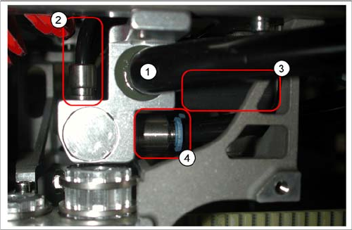
Pneumatic distributor under the gantry head distributor
Legend
1. Input: Exhaust Venturi nozzle pneumatic hose
(PK12)
2. Input: 7-fold pneumatic hose (PK 5)
3. Silencer for exhaust (only indicated in the diagram)
4. Compressed air outlet for pickup/placement circuit
and holding circuit
D1/2/D1i/D2i: to T distributor C&P/P&P head
D4/D4i: to C&P head