00195440-05-SG_D-Series_FSE-EN.pdf - 第139页
8 Gantry 8.4.1 Travel Ranges and Speed Monitoring at th e D4/D4i (A364) 8. 4 Settings Student Guide SIPLACE D-Series (FSE) 139 Travel ranges for X and Y axes (D4/D4i and X4 shown as example) The end of the X-axis travel …
8 Gantry
8.3 Pneumatic Connections on the Gantry 8.4.1 Travel Ranges and Speed Monitoring at the D4/D4i (A364)
138 Student Guide SIPLACE D-Series (FSE)
8.3
8.3 Pneumatic Connections on the Gantry
Pneumatic Connections on the Gantry
The placement head is supplied with 5.1 bar compressed air from the pneumatic unit.
D4/D4i/D2/D2i/D1/D1i: The 7-fold pneumatic hose is also used to cool the Y-axis motor. The X-axis mo-
tor is cooled by the traverse fan.
8.4
8.4 Settings
Settings
For detailed information about the assemblies and their settings, refer to the service guide for the respec-
tive machine.
8.4.1
8.4.1 Travel Ranges and Speed Monitoring at the D4/D4i (A364)
Travel Ranges and Speed Monitoring at the D4/D4i (A364)
The travel range of the X- and Y-axes is determined automatically with the SITEST program.
This means that, during travel range calibration, the axis concerned moves stepwise towards the mini-
mum or maximum position, until the set target value is no longer reached by the axis. It is then assumed
that the hardware limit switch (bumper) has been reached. After a time window of approx. 10 ms, the
greatest actual value achieved is taken to calculate the travel range.
To guarantee an appropriate safety distance before the hardware end position is reached, a certain dis-
tance is deducted from the set travel range and is defined as the software end position for the axis. This
enables the axis to brake in time, even when errors occur.
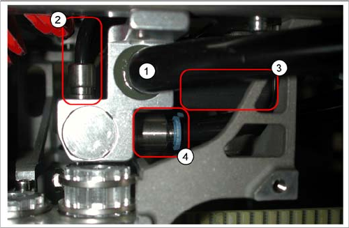
Pneumatic distributor under the gantry head distributor
Legend
1. Input: Exhaust Venturi nozzle pneumatic hose
(PK12)
2. Input: 7-fold pneumatic hose (PK 5)
3. Silencer for exhaust (only indicated in the diagram)
4. Compressed air outlet for pickup/placement circuit
and holding circuit
D1/2/D1i/D2i: to T distributor C&P/P&P head
D4/D4i: to C&P head
8 Gantry
8.4.1 Travel Ranges and Speed Monitoring at the D4/D4i (A364) 8.4 Settings
Student Guide SIPLACE D-Series (FSE) 139
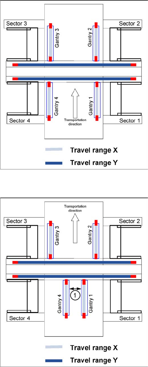
Travel ranges for X and Y axes (D4/D4i and X4 shown as
example)
The end of the X-axis travel range (software end position)
is 0.5 mm before the hardware end position, which is 1.5
mm before the bumper. A safety distance of 2.0 mm to
the bumper is adequate, if the X-axis moves into this area
with excessive speed.
The end of the Y-axis travel range (software end position)
is 1.5 mm before the hardware end position. The Y-axis
travel range for a particular placement area is monitored
in one direction by the software end position and a bump-
er. In the other direction, the travel range is calculated
from the position of the opposite gantry. A mutual gantry-
gantry position query is issued, which regulates the start
of the Y axes. The communication exchange is via the
SPI bus (Small Processor Interface bus) between the Y
axes and reports their positions and speed (see descrip-
tion of anti-crash function). The safety distance between
the gantry bumpers is 4 mm during placement.
Travel ranges and safety distances for gantry axes (D4/
D4i and X4 shown as example)
1. This means that, during travel range calibration, the
X-axis moves as far as possible towards the mini-
mum or maximum position, until it touches the bump-
er.
The travel ranges are calculated, taking into account
the relevant safety distance.
2. In placement areas 1 and 2 of the D4/D4i, gantry 1/2
moves to the minimum position and gantry 4/3 to the
maximum position, for calculation of the Y-axis travel
range.
3. The safety distance (1) between the sides of the gan-
try facing each other is at least 4mm, during place-
ment.

8 Gantry
8.4 Settings 8.4.2 Gantry Settings
140 Student Guide SIPLACE D-Series (FSE)
8.4.2
8.4.2 Gantry Settings
Gantry Settings
Settings/checks
Assembly Tools & equip-
ment *
Setting type Comments See also
X-drive
X-motor D1/
D1i/D2/D2i
Belt tension
measuring de-
vice
X belt is set at tensioning key to 44 +/
-1 Hz / axis dynamics
D4/D4i / D2/D2i/
D1/D1i measure
at front belt if the
head is at far left,
against X motor.
SA
X belt D1/D1i/
D2/D2i
Belt tension
measuring de-
vice
X belt is set at tensioning key to 44 +/
-1 Hz / axis dynamics
X deflection
unit D1/D1i/
D2/D2i
Belt tension
measuring de-
vice
X belt is set at tensioning key to 44 +/
-1 Hz / axis dynamics
X-motor D4/
D4i
Belt tension
measuring de-
vice
X belt is set at tensioning key to 53 +1/
-3 Hz / axis dynamics
SA
X belt D4/D4i Belt tension
measuring de-
vice
X belt is set at tensioning key to 53 +1/
-3 Hz / axis dynamics
X deflection
unit D4/D4i
Belt tension
measuring de-
vice
X belt is set at tensioning key to 53 +1/
-3 Hz / axis dynamics
X brake Screw in screw as far as possible,
with defined spring tension.
X drive mag-
nets (second-
ary part)
Glued to CFK gantry – not individually
replaceable
D3 only
X-axis incre-
mental encod-
er
0.4 mm foil Align encoder to scale & with 0.4 mm
space to scale / axis function – dy-
namics?
Align to count
track - fiducials on
encoder
X incremental
scale
0.4 mm space to scale / axis function
– check dynamics.
Reserved for
Siplace Service,
for D2/D2i/D1/D1i
D3 - glue in place
/ for D4/D4i screw
in place
Y drive Linear motor
Y drive mag-
nets (second-
ary part)
0.8 mm space below and between the
boards
D/Di-series
Y brakes Pretension due to gantry suspension D/Di-series
Y-axis incre-
mental encod-
er
0.4 mm foil Align encoder to scale & with 0.4 mm
space to scale / axis function – dy-
namics?
Align to count
track - fiducials on
encoder
Y incremental
scale
Align along the Y guide rail with spe-
cial tool/ 0.4 mm space to scale / axis
function – check dynamics in continu-
ous run.
Reserved for
Siplace Service -
different gauges
to be glued in
place, for D4/D4i/
D3/D2/D2i/D1/D1i