00195440-05-SG_D-Series_FSE-EN.pdf - 第147页
9 C&P Placement Heads 9.1.4 C&P Head Placement Construction 9.1 Overview Student Guide SIPLACE D-Series (FSE) 147 9.1.4 9 . 1 . 4 C & P H e a d P la c e m e n t C o n s t r u c t io n C&P Head Placement C…
9 C&P Placement Heads
9.1 Overview 9.1.2 Camera Modularity on C&P 12 Head
146 Student Guide SIPLACE D-Series (FSE)
9.1.2
9.1.2 Camera Modularity on C&P 12 Head
Camera Modularity on C&P 12 Head
Technical data - component cameras
9.1.3
9.1.3 Overview of C&P6/12 Head Parts
Overview of C&P6/12 Head Parts
NOTICE
Cause of Hazard
The standard camera on the C&P12 is the 28.sst, although the component camera 29.sst, with
a higher resolution (for small 0201 components), can be installed as an option (the same max-
imum component dimensions apply in this case)
Smaller maximum component dimension apply when using the SST38 camera option. For fur-
ther settings and data for the C&P12 head, see the specifications for the relevant option.
For Di-series (for small 0201 and 01005 components), component camera 30 sst will replace
component camera 29 sst and 38 sst respectively.
Description 12 segment standard
SST 28
12 segment with SST 29 12 segment with SST 30
Component size:
Flip Chip/Bare Die
0.3mm x 0.3 mm (0201) to 18.7 mm x 18.7 mm 0.18mm x 0.18mm
(01005) to 27mm x
27mm
Component height 0.15 mm up to 6 mm 0.15 mm up to 6 mm 0.15 mm up to 6 mm
Placement accura-
cy
+/- 80 µm at 4 (Sigma) +/- 55 µm at 4 (Sigma)
Angular accuracy +/- 0.7° at 4 (Sigma) +/- 0.7° at 4 (Sigma)
Resolution of com-
ponent camera
50µm/pixels 26µm/pixels 17µm/pixels
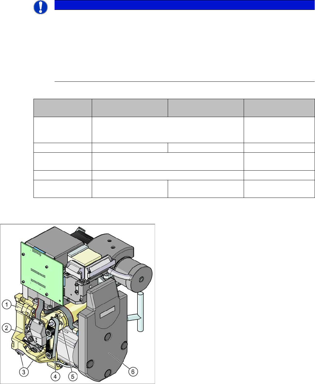
C&P12 head
Legend - overview of parts 1
1. Collect&Place head 12 (DLM3)
[03041228-xx] (shown)
Collect&Place head 6 (DLM3)
[03048341-xx] (not for D4/D4i)
2. Light barrier "Z axis up " (behind the cover)
[00347297-xx]
3. Placement circuit valve positioning drive
[00368076-xx]
Reject circuit valve positioning drive
[00368074-xx]
4. Z axis toothed belt
[00334936-xx]
5. Z axis drive
[03038908-xx]
6. Intermediate distributor, digital (behind the cover)
[00330648-xx]
9 C&P Placement Heads
9.1.4 C&P Head Placement Construction 9.1 Overview
Student Guide SIPLACE D-Series (FSE) 147
9.1.4
9.1.4 C&P Head Placement Construction
C&P Head Placement Construction
9.1.4.1
9.1.4.1 Hardware - new features for C&P head
Hardware - new features for C&P head
The D4/D4i does not have a Head Modularity function, as this machine is designed to succeed the HS,
as a fast placement machine for small components.
The placement heads on the D/Di-series have the following common/different features:
Hardware - new features for C&P head
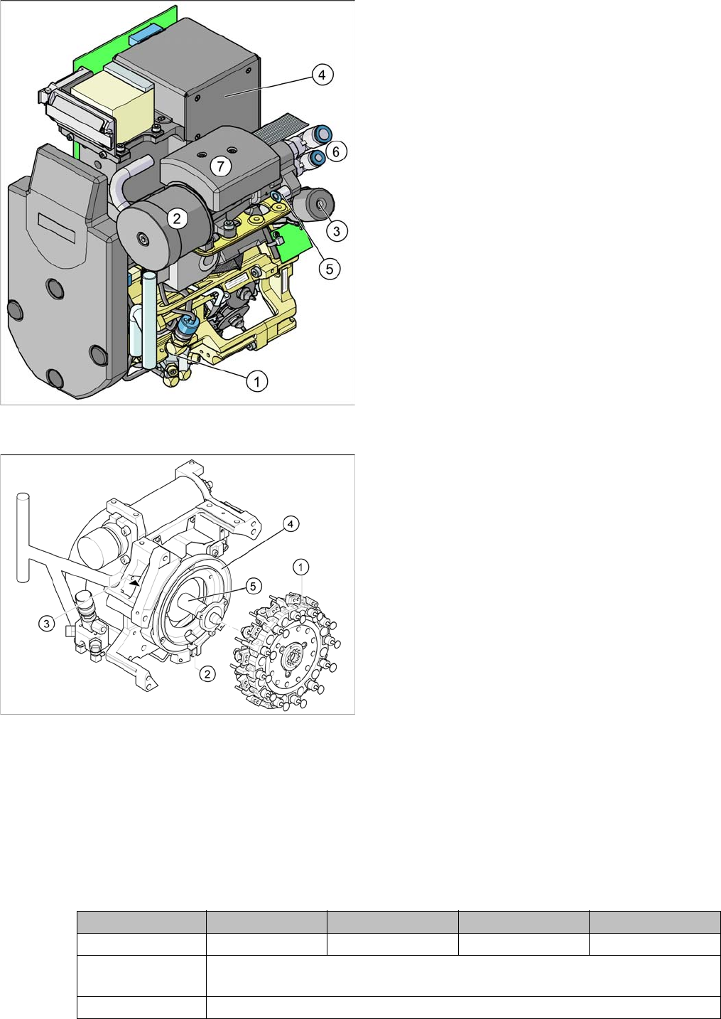
C&P12 head
Legend - overview of parts 2
1. Forced air unit with electromagnetic valve (version 02
– backwards compatibility)
[00367793-xx]
2. Silencer
[03003134-xx]
3. Turning station
[00341780-xx]
4. Component camera 18x18
[03014449-xx]
Component camera 27x27(sst29)
[03018637-xx]
Component camera 27x27(sst30)
[03085394-xx] (for Di-series)
5. Compressed air connection for forced air unit
6. Compressed air supply for vacuum generator (hold
circuit and pickup/place)
7. Vacuum measuring board (under the cover)
C&P12 head
Legend - overview of parts 3
1. Star, Fitted
2. "Z axis down" sensor
3. RSF digital encoder 12/DLM2
4. Circular arc guide (raceway), aligned to star drive
axis
5. Star drive axis, centered by head housing and Z axis
claw
Assembly D4/D4i D3 D2/D2i D1/D1i
C&P head types C&P12 C&P12 or 6 C&P12 or 6 C&P12 or 6
Star drive ‚C28’
03031187-01
New bearings / strengthened motor shaft / green heat-shrinkable sleeve for star
axis incremental encoder cable
Forced air unit 00367793-02 Neue Version 02: with date printed on the e-valve

9 C&P Placement Heads
9.1 Overview 9.1.4 C&P Head Placement Construction
148 Student Guide SIPLACE D-Series (FSE)
9.1.4.2
9.1.4.2 Placement Head Differences Between DLM 2/1 and DLM3
Placement Head Differences Between DLM 2/1 and DLM3
Placement Head Differences Between DLM 2/1 and DLM3
9.1.4.3
9.1.4.3 Kamera-Modularität
Kamera-Modularität
Camera equipment for C&P head options
DP station 00341780-05 version 5, downwards compatibility
Valve positioning
drives
Version 02
Requirements Minimum 601.03 SP1 or A364 axis controller (for Di must be 605.03 SP2)
Head modularity No Same as X ma-
chines
Reconfig. set
C&P12 head
00119860-01
Reconfig. set C&P6
head 00119861-01
Special features Component sensor fasteners for C&P12 with 130Ncm
Neuer Pinolenras-
tring
(verfügbar ab ...2008) (Nachrüstung für ältere Bestückkopftypen nur durch Ser-
vice)
Version 6 der
DP-Station
(verfügbar ab ca. Juni 2008)
Version 03 der Bla-
slufteinheit
(verfügbar ab ca. Juni 2008)
Assembly D4/D4i D3 D2/D2i D1/D1i
Assembly DLM 1/2 DLM 3
C&P head type C&P12 und 6 C&P12 or 6
Bestücksternantrie
b ‚C28’ [03031187-
01]
Neue Lagerung / stärkere Motorwelle /
grüner Schrumpfschlauch an der Inkre-
mental-Encoderleitung Sternachse Neue
Maschinen-Daten
Placement star
drive ‚C29’
Compatible fitting for DLM1 and 2
Blaslufteinheit
Version 02
Downwards compatibility YES
Blaslufteinheit Ver-
sion 03
Downwards compatibility
(verfügbar ab ca. 06/2008)
Downwards compatibility
(verfügbar ab ca. 06/2008)
DP station [00341780-05] (Version 5), wird abgelöst durch
Version 6 (verfљbar ab ca. 06/2008) (abwärtskompatibel)
Valve positioning
drive
Version with original cam disk DLM1 /
new cam disk DLM2
DLM2 cam disk and version 2
Requirements Minimum SC/MC 601.03 SP1 or A364
axis controller
Special features Befestigung BE-Sensor C&P12 mit 130 Ncm
Camera D4/D4i
with C&P12
D3
with C&P12
D2/D2i
with C&P12
D1/D1i
with C&P12
Standard C&P12 SST28
Als hochauflösende Version SST29 (SST30 for Di-series)
C&P12 mit extremhochauflösender
Kamera für 0402 mm (01005)
SST38 (SST30 for
Di-series)
--- SST38 (SST30 for
Di-series)
Standard C&P6 --- SST29 (SST30 for Di-series)