00195440-05-SG_D-Series_FSE-EN.pdf - 第150页
9 C&P Placement Heads 9.1 Overview 9.1.4 C&P Head Placement Construction 150 Student Guide SIPLACE D-Series (FSE) 9.1.4.6 9 . 1 . 4 . 6 N o z z le C h a n g e r f o r 1 2 S e g m e n t C & P H e a d Nozzle Ch…
9 C&P Placement Heads
9.1.4 C&P Head Placement Construction 9.1 Overview
Student Guide SIPLACE D-Series (FSE) 149
9.1.4.4
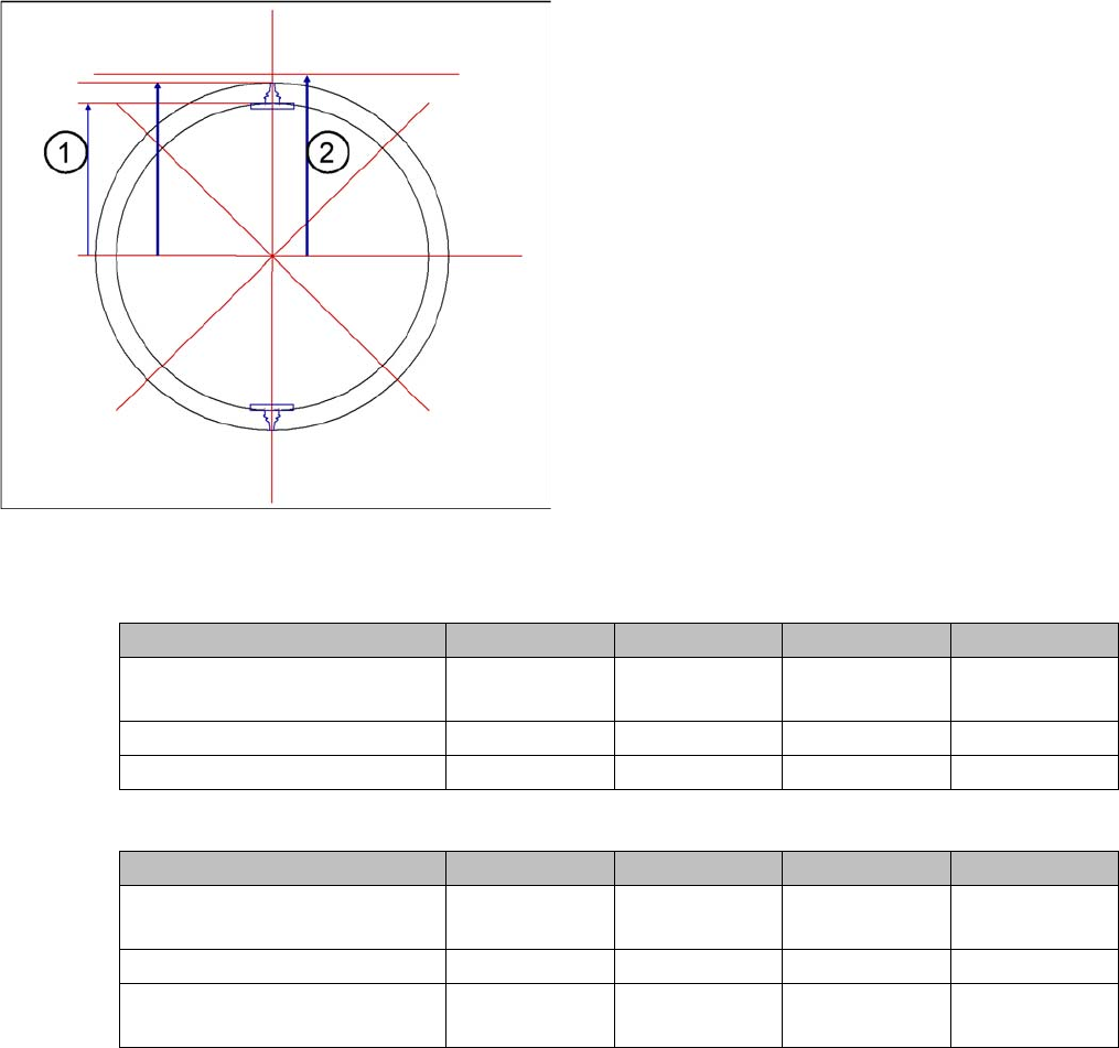
9.1.4.4 Focus Level of C&P Component Camera
Focus Level of C&P Component Camera
9.1.4.5
9.1.4.5 Nozzle Changer Features
Nozzle Changer Features
PPW-Ausrüstungen C&P12-Bestückkopf
PPW-Ausrüstungen C&P6-Bestückkopf
The digital component camera has a pixel size correction
function in case the calculated component level deviates
too greatly from the theoretical focus level.
If the “placement head radius (1) plus nozzle length plus
component height“ data deviates from the theoretical fo-
cus level (2), an appropriate correction pixel size factor is
derived from this.
In der Pipettenprogrammierübersicht bekommen Sie zu
den einzelnen Typen einen Höhenwert als Anhaltspunkt,
den Sie so auch für die Kameras mit ICOS-System
übernehmen können.
Features for C&P12 D4/D4i D3 D2/D2i D1/D1i
Number of NC carriers per gan-
try
1 HS compati-
ble
2 X compatible 1 new 1 new
Anzahl der Magazine pro Träger5555
Supply pressure 5 bar 2.5 bar 2.5 bar 2.5 bar
Features for C&P6 head D4/D4i D3 D2/D2i D1/D1i
Number of NC carriers per gan-
try
--- 2 X compatible 1 new 1 new
Anzahl der Magazine pro Träger --- 6 6 6
Length of NC carrier (outer edg-
es)
475 mm 450 mm 565 mm 565 mm
9 C&P Placement Heads
9.1 Overview 9.1.4 C&P Head Placement Construction
150 Student Guide SIPLACE D-Series (FSE)
9.1.4.6
9.1.4.6 Nozzle Changer for 12 Segment C&P Head
Nozzle Changer for 12 Segment C&P Head
Optionally, a nozzle changer can be installed for each C&P head. This enables the nozzle configuration
to be changed quickly, thus allowing the Collect&Place head to be quickly adapted to the needs of the
placement process.
The nozzle changer consists of at least one and up to five magazines, each of which is equipped with
up to twelve nozzle garages. The magazines are seated on a common support and each magazine is
centered using two pins and is fixed in place with a spring hook.
Each garage can be configured with different nozzle types.
9.1.4.7
9.1.4.7 Neuerungen in der SW
Neuerungen in der SW
Vorbereitet in 603 und aktiviert in 604 wurde die Möglichkeit zusätzlicher Prüfungen und aktiviert mit SC/
MC 604.01 SP1 (seit 01.2008) (& bei SC/MC 503.04 SP2/ 505.04):
▪ For early vacuum with 901/911/904/914/925 nozzles for 'early vacuum' – additional vacuum check
ModeVacOpenCheck="2" – Es wird die Fehlermeldung 3570 "BE an Pipette vor Abholen bzw. Pi-
pette verschmutzt." ausgegeben.
VacOpenBeforePickup="55"
During the upwards movement in 'early vacuum' mode, a vacuum check is performed for the seg-
ment, with open vacuum valve. The vacuum value measured must be 55 mbar less than the closed
value.
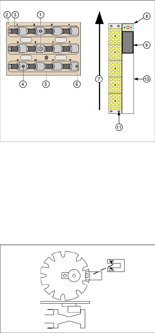
Nozzle changer and nozzle magazine for C&P12 (D4/D4i
shown as example)
Legend
1. Calibration fiducial on magazine
2. Locking plate
3. Nozzle garage
4. Hole for centering pin, for exact positioning of maga-
zine
5. Hole for driver pin, for opening and closing of maga-
zine
6. Slit for centering pin, for exact positioning of maga-
zine
7. Transport direction
8. Nozzle reject device
9. Nozzle reject container
10. Tape duct
11. Fastening screws for nozzle changer (4x)
Rotated by 90° to activate vacuum
In the 9xx nozzle parameters, a value has been created
which allows the time for component pickup with the C&P
head to be controlled. In this case, you need to use the
special cam disk, so that you do not need to wait for the
entire 90° travel range (2nd 90° rotation at Z up) and still
have enough vacuum for a successful pickup. See Dura-
tionZaxisDown.
This mode differs by up to 4 ms from the usual times. This
means: using the 'old' cam disk (DLM1) at the valve posi-
tioning drive takes 10ms (typically) / using the 'new' cam
disk (DLM2 – see diagram) takes approx. 8 ms / using the
new mode then takes about 6 ms.
9 C&P Placement Heads
9.1.5 Compressed Air Supply on C&P Head 9.1 Overview
Student Guide SIPLACE D-Series (FSE) 151
▪ Ein zusätzlicher Z-Höhencheck der die Abholhöhe für Pipetten 925 und 914/904 oder kleiner prüft:
ModeZAxisCheck="2" – Es wird die Fehlermeldung 3573 "Pipette verschmutzt bzw. Hindernis beim
Abholen." ausgegeben.
HeightZAxisMin="200"
HeightZAxisMax="1000"
Wird die theoretische Abholhöhe um mehr als z. B. 200 µm (vom Typ der Pipette abhängig) unter-
schritten (Zielposition nicht erreicht/höher), so reagiert die Stationssoftware mit der Fehlermeldung
3573 "Pipette verschmutzt bzw. Hindernis beim Abholen.". Die Pipette wird gereinigt und versucht,
das Bauelement nochmals abzuholen.
9.1.5
9.1.5 Compressed Air Supply on C&P Head
Compressed Air Supply on C&P Head
The compressed air for D1/D1i/D2/D2i machines is distributed via an additional T-piece and small com-
ponent sets with pneumatic hoses to the two placement heads.
9.1.5.1
9.1.5.1 Vacuum Generator
Vacuum Generator
9.1.5.2
9.1.5.2 Placement Head Function Check
Placement Head Function Check
Before the 1st reference run or with released Z and star axis:
Check Z axis:
▪ Rotate the star so that one segment is in the star pickup/place position.
▪ Position the Z axis up and down on the belt. The LED light barrier (LB) Z up will shine (down) or ex-
tinguish (up).
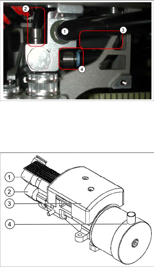
Pneumatic distributor under the gantry head distributor
Legend
1. Input: Exhaust Venturi nozzle pneumatic hose
(PK12)
2. Input: 7-fold pneumatic hose (PK 5)
3. Silencer for exhaust (only indicated in the diagram)
4. Compressed air outlet for pickup/placement circuit
and holding circuit
D1/D1i/D2/D2i: to T distributor C&P/P&P head
D4/D4i: to C&P head
Vacuum generator
Legend
1. Hold circuit supply
2. Placement and pickup circuit for blast air supply
3. Vacuum measuring board
4. Discharged air from the vacuum generator to the si-
lencer in the compressed air distributor